
Chapter-4
EXPLORING SOME
GEOMETRIC THEMES
In this chapter, we will explore two geometric themes. We will study fractals which are self-similar shapes. They exhibit the same or similar pattern over and over again-but at smaller and smaller scales. We will then look at different ways of visualising solids.
4.1 Fractals
One of the most beautiful examples of a fractal that also occurs in nature is the fern. The fern is seen to have smaller copies of itself as its leaves, and these in turn have even smaller copies of themselves in their sub-leaves, and so on!
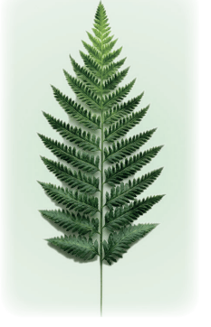
Similar phenomena of self-similarity occur in trees (where a trunk has limbs, and a limb has branches, and the branches have branchlets, and so on), clouds, coastlines, mountains, lightning, and many other objects in nature.
Other mathematical fractals can also be very beautiful. We will explore some of them here.
Sierpinski Carpet
The Polish mathematician Sierpinski discovered a type of fractal known as the Sierpinski Carpet. It is made by taking a square, breaking it into 9 smaller squares, and then removing the central square (see the figure below); the same procedure is then repeated on the remaining 8 squares, and so on. One then sees the same pattern at smaller and smaller scales.
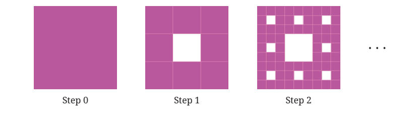
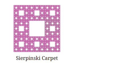
? Draw the initial few steps (at least till Step 2) of the shape sequence that leads to the Sierpinski Carpet.
By its construction, each step in the sequence has
(i) squares of the same size that remain in the figure, and the size of these squares becomes smaller and smaller as the step number increases, and
(ii) square holes that are formed by removing square pieces.
? Do you see any pattern in the number of holes and squares that remain at each step?
Let Rn represent the number of remaining squares at the nth step, and Hn represent the number of holes at the nth step.
Let us understand how these numbers grow by analysing how the holes and squares that remain are generated from the previous step.
Every square that remains at a given step, say Step n, gives rise to 8 squares that remain at the (n + 1) th step. Thus, we have
R n + 1 =8Rn .
? Can this be used to get a formula for Rn ?
We have
R0 = 1R1 = 8 *1=8
R2 = 8 *8=82
.
In general, R n = 8 n
? Similarly, how do we find the number of holes at a given step?
Every square that remains at the nth step gives rise to a hole in the (n + 1) th step. All the holes present at the nth step remain in the (n + 1) th step as well. Thus,
H n + 1 =H n +R n .
So we have
| R0 = 1 R1 = 8 R2 = 82 R3 = 83 |
H0 = 0 H1 = 1 H2 = 1 + 8 H3 = 1 + 8 + 82 |
Sierpinski Gasket
Sierpinski came up with another fractal made in a similar way. An equilateral triangle is broken up into 4 identical equilateral triangles by joining the midpoints of the bigger triangle, and then the central triangle is removed. This procedure is repeated on the 3 remaining triangles, and so on.
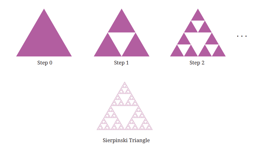
? Show that by joining the midpoints of an equilateral triangle, we divide it into 4 identical equilateral triangles.
[Hint: Note that the corner triangles are isosceles.] This fractal is called the Sierpinski Triangle/Gasket.
? Figure it Out
1. Draw the initial few steps (at least till Step 2) of the shape sequence that leads to the Sierpinski Triangle.
2. Find the number of holes, and the triangles that remain at each step of the shape sequence that leads to the Sierpinski Triangle.
3. Find the area of the region remaining at the nth step in each of the shape sequences that lead to the Sierpinski fractals. Take the area of the starting square/triangle to be 1 sq. unit.
Koch Snowflake
The Koch Snowflake is another fractal, named after the Swedish mathematician Von Koch, who first described it in 1904. We have already encountered this fractal in Grade 6, Ganita Prakash.
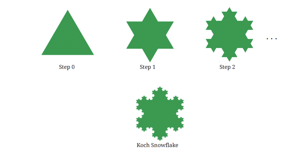
To generate it, we start with an equilateral triangle. Each side is
(i) divided into 3 equal parts, and
(ii) an equilateral triangle is raised over the middle part, and then the middle part is removed.
Effectively, each side gets replaced by a 'bump' - shaped structure This procedure is repeated on the sides of the new resulting shape, and so on.
?Figure it Out
1. Draw the initial few steps (at least till Step 2) of the shape sequence that leads to the Koch Snowflake.
2. Find the number of sides in the nth step of the shape sequence that leads to the Koch Snowflake.
3. Find the perimeter of the shape at the nth step of the sequence. Take the starting equilateral triangle to have a sidelength of 1 unit.
Fractals in Art
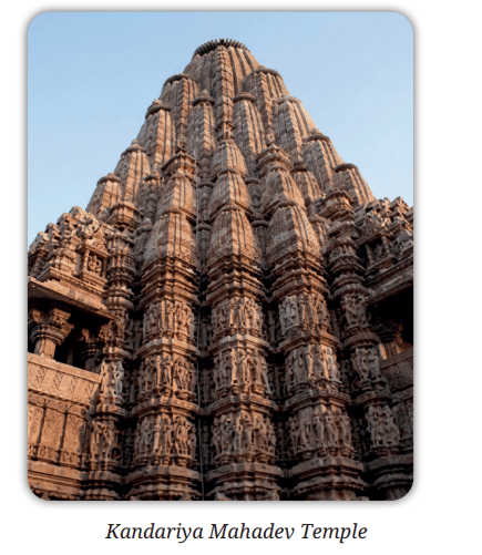
Fractals have also long been used in human-made art! Perhaps the oldest such fractals appear in the temples of India. An example occurs in the Kandariya Mahadev Temple in Khajuraho, Madhya Pradesh which was completed in around 1025 C.E.; there one sees a tall temple structure, which is made up of smaller copies of the full structure, on which there are even smaller copies of the same structure, and so on. Fractal-like patterns also occur in temples in Madurai, Hampi, Rameswaram, Varanasi, among many others.
Fractals are also common in traditional African cultures. For example, patterns on Nigerian Fulani wedding blankets often exhibit fractal structures.
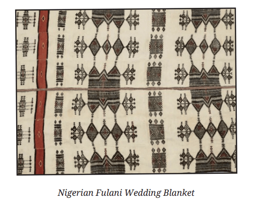
In the blanket shown in the figure, there are diamond shaped patterns, inside of which there are smaller diamond shaped patterns, and so on.
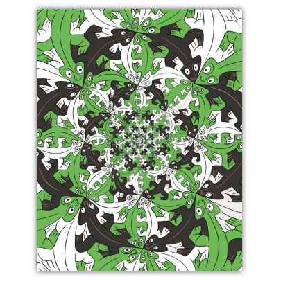
The modern maestro of fractal art is undoubtedly the Dutch artist M.C. Escher. We have already seen that some of his prints explore the mathematical theme of tiling. One famous example involving fractals is his work 'Smaller and Smaller', which exhibits the identical pattern of lizards but at smaller and smaller scales. Here is a print inspired by Escher's 'Smaller and Smaller'.
4.2 Visualising Solids
Build it in Your Imagination
? We will start this section by practising visualisation. For each prompt, feel free to talk to your partner, gesture, draw it in the air-but do not actually draw on paper!
-Nikolas Tesla (1856-1943), the great Serbian-American engineer and inventor, who made fundamental contributions to electrical engineering and other fields.
1. Picture your name, then read off the letters backwards. Make sure to do this by sight, not by sound-really see your name! Now try with your friend's name.
2. Cut off the four corners of an imaginary square, with each cut going between midpoints of adjacent edges. What shape is left over? How can you reassemble the four corners to make another square?
3. Mark the sides of an equilateral triangle into thirds. Cut off each corner of the triangle, as far as the marks. What shape do you get?
4. Mark the sides of a square into thirds and cut off each of its corners as far as the marks. What shape is left?
When we see a solid object, we are really seeing its profile from a specific viewpoint. Depending on our viewpoint, the outline of this profile can vary dramatically!
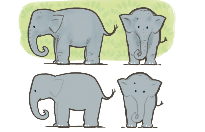
Perhaps you've noticed interesting profiles of objects yourself, while taking a photograph or observing the shadow of an object? Or, maybe you've seen a cartoon like the following, in which a character bursts through a wall and leaves a hole shaped like their outline!
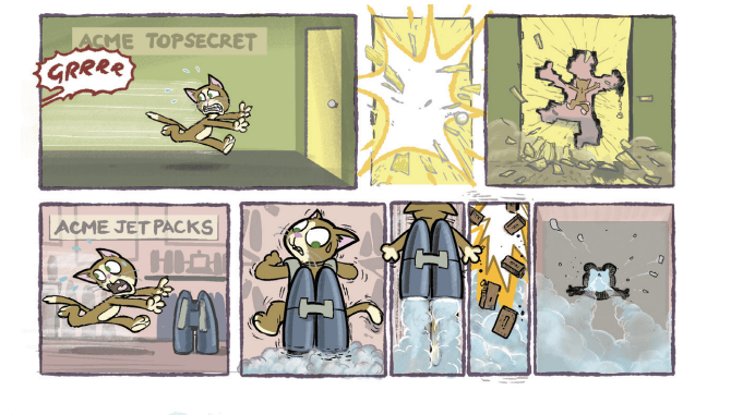
In previous classes, you’ve seen solids that are much simpler than an elephant or cat, such as cubes, spheres, cylinders, and cones. What would the profiles of these look like, from different viewpoints?
?Can you describe a solid and a viewpoint that would result in each of the following cases? If it helps, you can imagine the solid passing through a wall like Tom did, and leaving a hole of the appropriate shape.
5. A solid whose profile has a square outline
6. A solid whose profile has a circular outline
7. A solid whose profile has a triangular outline
? As we saw with the elephant, a given solid might have very different profiles from different viewpoints. Can you visualise solids that have the following contrasting profiles?
Spend some time on this, and if you are finding it difficult to visualise, you may look around and use objects that are around you, or that you will make in the next section. Feel free to consider viewpoints from any direction, including directly above the object.
8. A solid with a rectangular profile from one viewpoint and a circular profile from another viewpoint
9. A solid with a circular profile from one viewpoint and a triangular one from another viewpoint
10. A solid with a rectangular profile from one viewpoint and a triangular one from another viewpoint
11. A solid with a trapezium shaped profile from one viewpoint and a circular one from another viewpoint
12. A solid with a pentagonal profile from one viewpoint and a rectangular one from another viewpoint
? Are there unique solids for each of the conditions, or can you come up with multiple possibilities?
Making Solids
Many basic solid shapes such as a cuboid, parallelopiped, cylinder, cone, prism, and pyramid can be made using foldable flat materials like paper, cardboard, and even metallic sheets! This is one of the methods for manufacturing hollow solids.
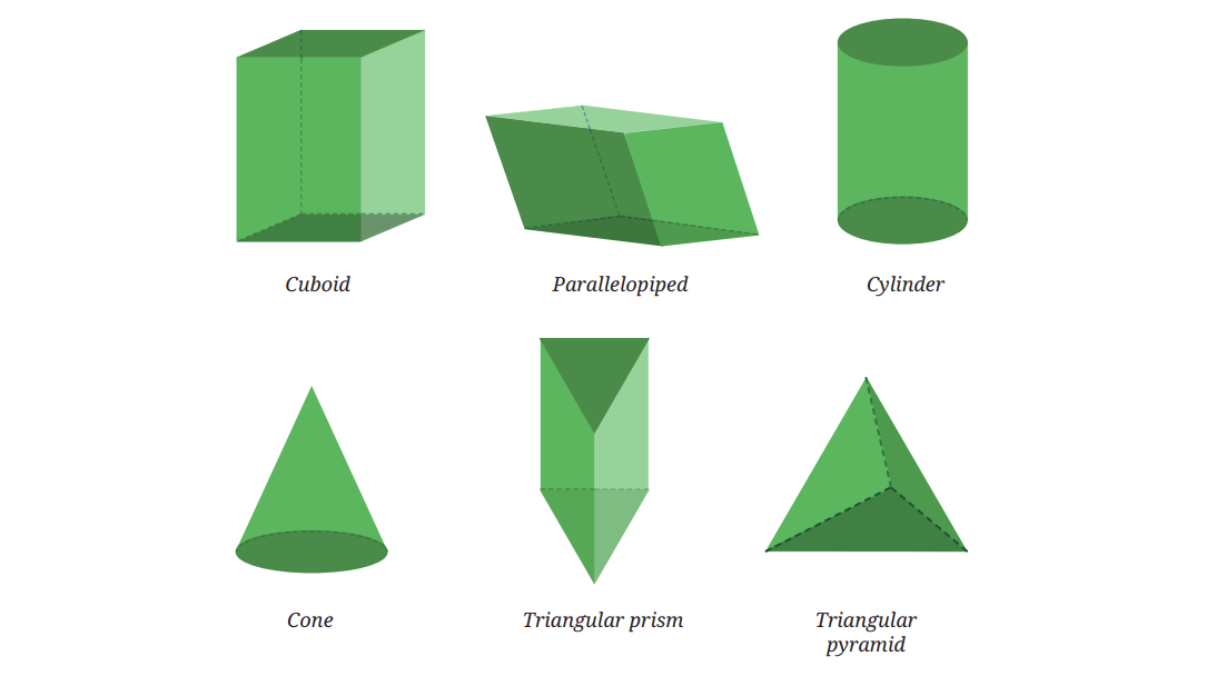
While discussing solids that contain plane surfaces in their boundaries, the notion of faces, edges and vertices serves a useful purpose.
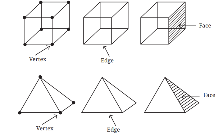
Faces are the plane/flat surfaces of a solid that form its boundary. Edges are the line segments that form the sides of the faces, and vertices are the points at which the edges meet. For example, a cuboid or cube has 6 faces, 12 edges and 8 vertices.
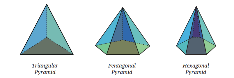
There are multiple types of prisms and pyramids, whose names depend on the shapes of their faces.
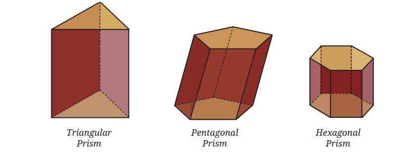
Prism: A prism, in general, has two congruent polygons as opposite faces, with edges connecting the corresponding vertices of these polygons. All the other faces are parallelograms. Based on the shape of the congruent polygons, prisms may be called triangular prisms, pentagonal prisms, and so on.
Pyramids: A pyramid, in general, has a polygonal base and a point outside it, and edges connect the point with each of the vertices of the base. Based on the shape of the base, pyramids may be called triangular pyramids, square pyramids, pentagonal pyramids, and so on. A triangular pyramid is also known as a tetrahedron.
? If the congruent polygons of a prism have 10 sides, how many faces, edges and vertices does the prism have? What if the polygons have n sides?
? If the base of a pyramid has 10 sides, how many faces, edges and vertices does the pyramid have? What if the base is an n-sided polygon?
Now we will see how to make different solids using a foldable flat surface such as paper, cardboard, etc.
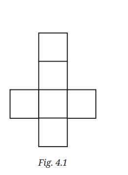
The basic idea is to create a shape on a flat surface that can be folded into the solid. Such a shape is called a net. In other words, a net. is obtained by ‘unfolding’ a solid onto a plane.
?What is a net of a cube?
Fig. 4.1 is a net of a cube.
?Visualise how it can be folded to form a cube.
 Practical Aspects of Using a Net
To make an actual cube from its net, certain practical aspects have to be kept in mind. One is that the material used must have sufficient sturdiness for the cube to stand. The second aspect is that there should be some mechanism for attaching the faces together. If cardboard or a similar material is used, cello tape is one way to join the adjacent faces. For less sturdy materials, such as chart paper, it is useful to have extra ‘flaps’ on some of the faces that can be stuck to the adjacent faces. You might have observed this strategy in packaging boxes.
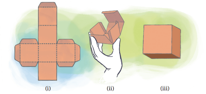
However, when we talk about the net of a solid, we consider only the shape formed by unfolding the solid, and not the other supporting flaps that we may use to actually make the solid.
Apart from using a net, there are other ways to make a cube from paper.
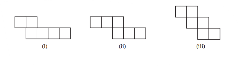
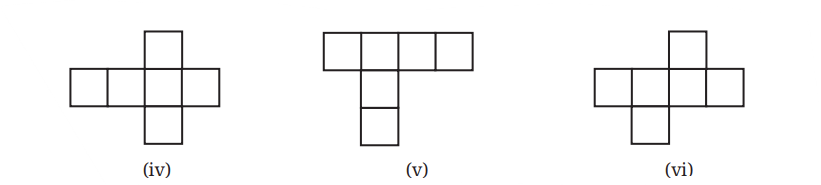
There are multiple possible nets one can use to build a cube.
? Figure it Out
1. Which of the following are the nets of a cube? First, try to answer by visualisation. Then, you may use cutouts and try.
2. A cube has 11 possible net structures in total. In this count, two nets are considered the same if one can be obtained from the other by a rotation or a flip. For example, the following nets are all considered the same —
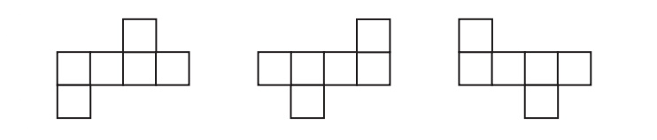
Find all the 11 nets of a cube.
3. Draw a net of a cuboid having sidelengths:
(i) 5 cm, 3 cm, and 1 cm
(ii) 6 cm, 3 cm, and 2 cm
Let us find out the nets of other solids.
A tetrahedron whose faces are equilateral triangles is called a regular tetrahedron.
? What is a net of a regular tetrahedron? Which of the following are nets of a regular tetrahedron?
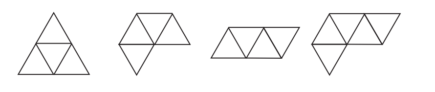
? Are there any other possible nets?
A regular tetrahedron has only 2 possible nets.
? Draw a net with appropriate measurements that can be folded into a regular tetrahedron. Verify if it works by making an actual cutout.
? Draw a net with appropriate measurements that can be folded into a square pyramid. Verify if it works by making an actual cutout.
? What is the net of a cylinder?
If the circular faces of a cylinder are unfolded, and if a cut is made along the height of the cylinder, as shown in the figure below, then we get
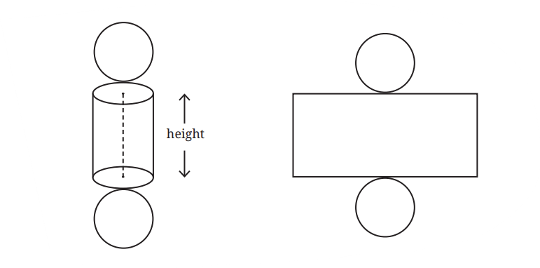
? What are the sidelengths of the rectangle obtained?
? How will the net of a cone look?
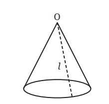
? If the cone is slit open along the line I and then unrolled, what will we get?
Observe that all the points on the boundary of the base circle are at equal distances from ` 0' So after unrolling the cone, the boundary of the net will be a portion of a circle with centre O.
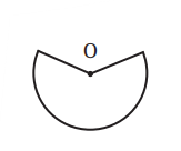
? What surface do you construct by using the above net, in which O is not the centre of the boundary circle? Make a physical model to help you answer this question!
? Draw a net with appropriate measurements that can be folded into a triangular prism. Verify that it works by making an actual cutout.
Here is a solid called the octahedron, made by joining two square pyramids at their square bases.
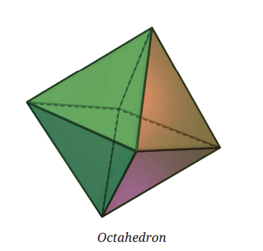
Can you visualise its net? This is one of its nets.
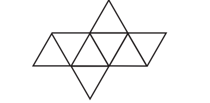
? Taking all the triangles in the net to be equilateral, make a cutout of the net and fold it to form an octahedron.
As in the case of cubes, an octahedron too has 11 different nets.
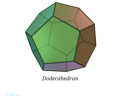
So far, we have seen solids whose faces are all equilateral triangles (regular tetrahedrons), and all squares (cubes). Does there exist a solid whose faces are all pentagons? Interestingly, the answer is yes!
This solid is called a dodecahedron. This solid too can be made from a net! Mathematicians have been even able to determine exactly how many nets a dodecahedron has-43,380.
? Net of a sphere? Experiment and see if you can make a paper cutout that can perfectly wrap around a ball without leaving any wrinkles, gaps or overlaps.
Shortest Paths on a Cube
Let us consider an interesting problem related to the discussion so far. We know that on a plane, the shortest path between two points is the straight line between them. Now, what is the shortest path between two points on the surface of a cuboid, if we are allowed to travel only along its surface
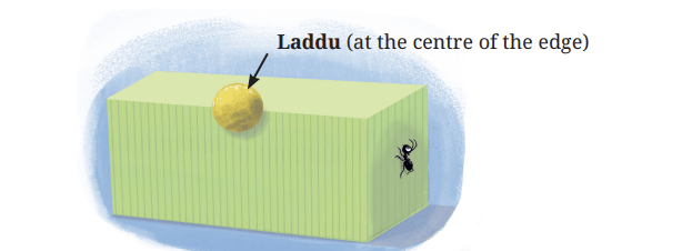
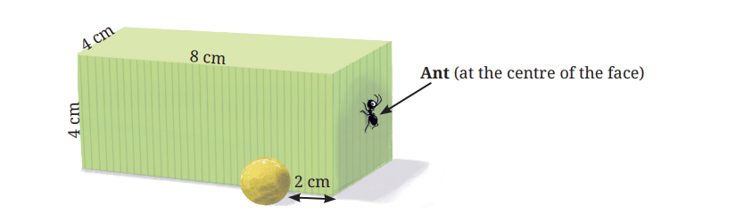
Let us imagine a hungry ant living on the surface of a cuboid. To its good fortune, there is a laddu on the surface.
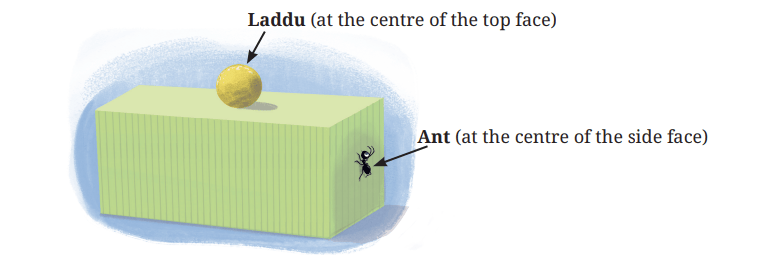
? What is the shortest path for the ant to reach the laddu?
? What about in the following case?
? If we think that a certain path is the shortest, how can we be sure that it truly is, among all the infinite possibilities?
? For example, are either of these the shortest path?
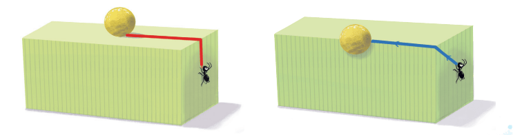
[Hint: Draw the net and see how these paths appear on the net.]
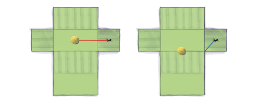
? What does this show?
A path on the surface of the cuboid can be transformed to a path of the same length on the net. Conversely, every path on the net transforms to a path of the same length on the cuboid.
In the first case, the path marked on the cuboid is the shortest since it transforms to a straight line between the ant and laddu on the net, which is the shortest path between them.
In the second case, the path marked on the cuboid does not transform to a straight line path on the net, and hence is not the shortest path for the ant to take.
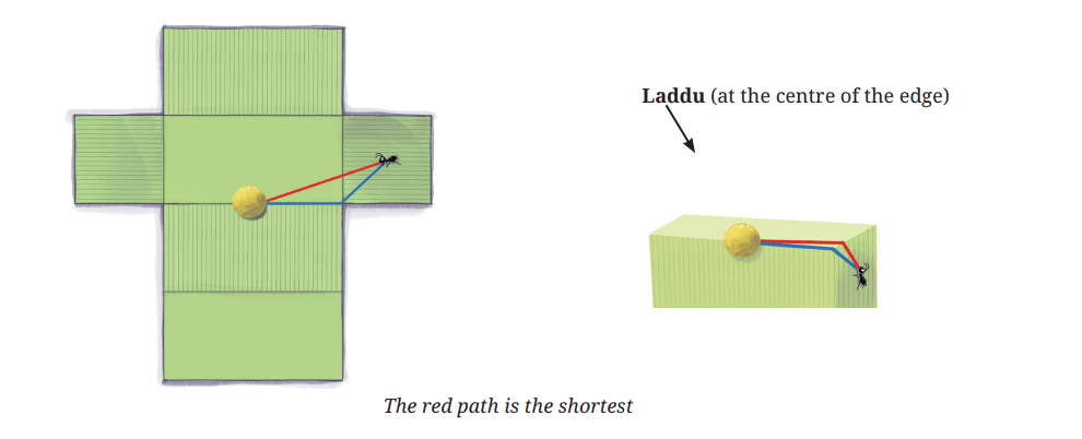
Thus, by using a net, we convert the problem of finding the shortest path on a cuboid to the problem of finding the shortest path on the net.
Have we now completely analysed the problem of finding the shortest path between two points on a cuboid?
? Find the shortest path between the ant and the laddu in the following case:
If we unfold the cuboid as before, we get
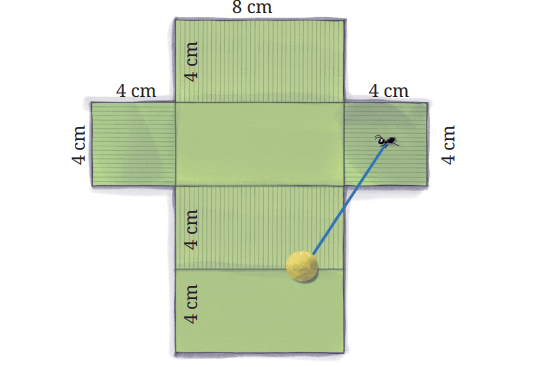
Notice the line segment between the ant and laddu going outside the net! Obviously, this does not correspond to any path on the cuboid.
? So what do we do now?
If the net is unfolded in the following way, then we get a path on the cuboid.
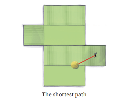
Thus, the way a cuboid is unfolded matters!
Now we will look at a trickier case.
? What is the length of the shortest path between the ant and the laddu?
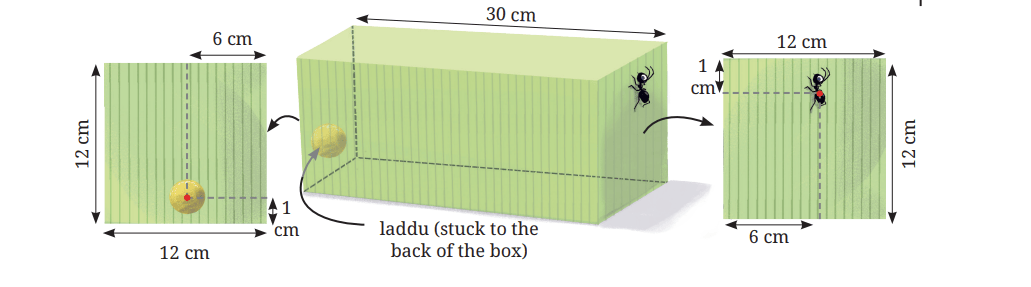
Here are some of the ways of unfolding the cuboid.
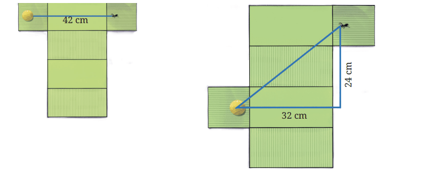
In the second case, the distance d between the ant and the laddu can be calculated using the Baudhayana Theorem, since we have a right triangle here.
d2 = 242 + 322
d = √1600= 40 cm
We see that in each of these unfoldings, the lengths of the line segments between the ant and the laddu are different! So we have to carefully list all the possible different unfoldings to find the answer!
Representation of Solids on a Plane Surface
Drawing is one of the oldest human activities. People have been doing it for thousands of years for both aesthetic as well as practical and engineering purposes. Regarding the latter, making a drawing of an object is a useful way to record or convey information about it. Visual representation also helps us in thinking about the objects being represented. Such needs often arise in engineering — while constructing buildings, designing machines, etc. Further, engineering drawings need to be detailed enough so that one can physically construct the objects they depict.
We will now explore some ways of drawing solids on a plane.
ProjectionsThe net of a solid (when it exists) is one way of representing a solid on the plane. But it can be difficult to visualise the solid from the net, without physically cutting out the net and folding it up.
Another way to represent a solid is by looking at the projections of all its points on a plane. This idea is closely related to the profile of a solid from a specific viewpoint, which we discussed earlier. Let us see how this technique works.
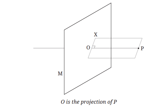
Consider a point P in space, and a plane M. Imagine a line from P intersecting the plane M at a point O.
We say that OP is perpendicular to the plane if for any line OX on the plane, ∠POX = 90°. In this case, we say that point O is the projection of point P on the plane. The projections of all the points of an object together form the projection of the object on the plane.
? Let us visualise the projection of a line.
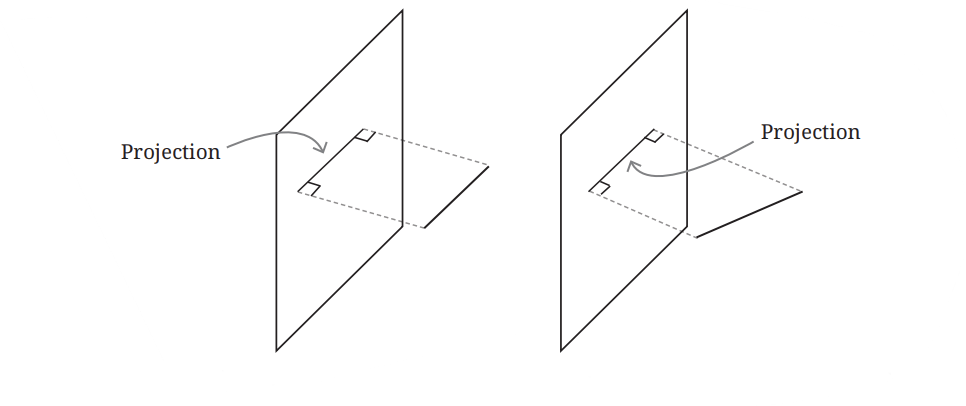
? What happens to the length of a line in its projection?
Let us consider projections in Fig. 4.3. For example let I be the actual length of the line and p be the length of its projection.
Draw AE ⊥ BC. AECD is a rectangle (why?). So, AE = DC = p Also, angle AEB = 90°
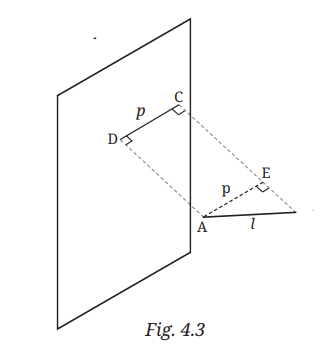
? Can you now compare the lengths p and l?
? When is the length of the projected line equal to its actual length?
? What do you think are the different possible projections of a square that we get based on its orientation?
Can this ever be a quadrilateral that is not a parallelogram? As a starting point, you could think about the projection of a pair of parallel lines.
? What can you say about the projection of an n-sided regular polygon? [Hint: Projection of a polygon is composed of the projections of its sides.]
Let us consider projections of solids now.
? How would the projections of a cube and a cone look?
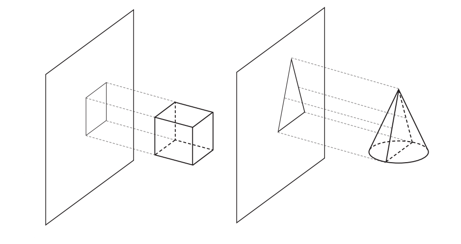
If an object were to pass perpendicularly through a plane and form a hole, the shape of the hole would be the same as the shape of the projection of the object.
? See Figures 4.2-4.5. In each case, see if you can visualise another object that gives the same projection.
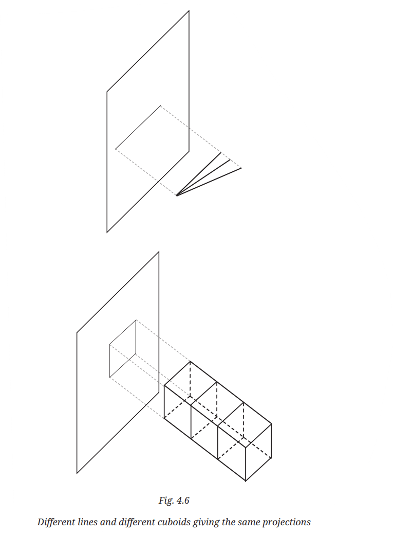
We see that a given projection is not made by a unique object.
? Find another object that makes the same projection as that of a given cone.
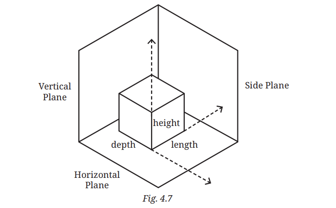
For this reason, we often take three mutually perpendicular projections of an object. As shown in the figure, we consider a plane in front of the object called the vertical plane, a plane below the object called the horizontal plane and a plane to the side of the object called the side plane.
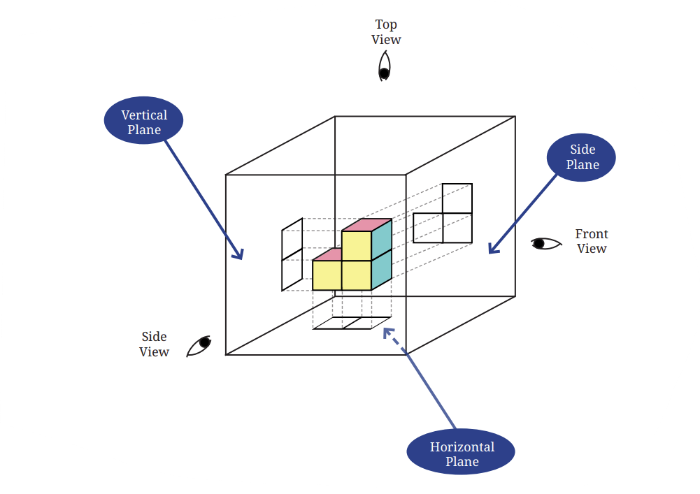
We give names to the projections on these three planes based on the directions from which the object is viewed. The projection on the vertical plane is called the front view, on the horizontal plane the top view and on the side plane the side view. These projections formalise the notion of profiles that we explored in an earlier section.
? Let us see what these projections are for the objects shown in Fig. 4.6, when the planes shown are taken to be vertical planes.
Projections of the different lines in Fig. 4.6 –
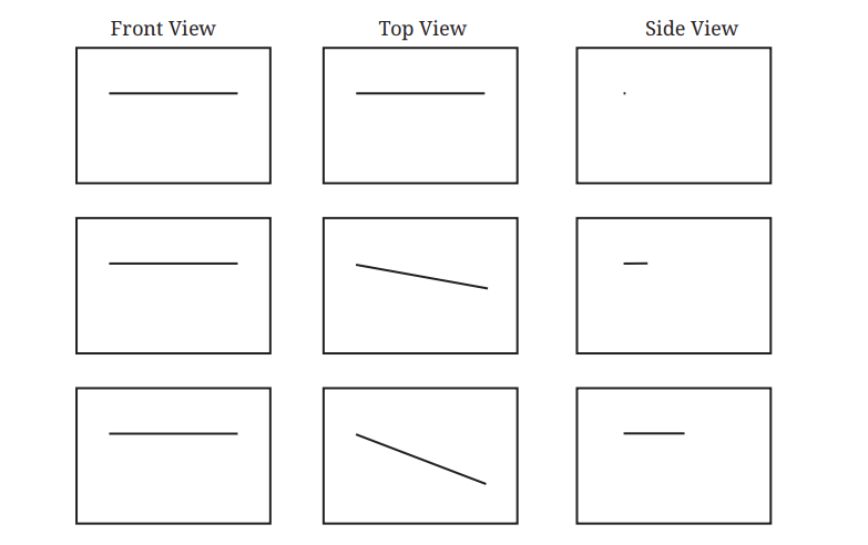
Projections of the different cuboids in Fig. 4.6 —
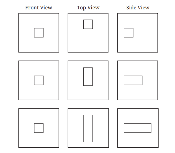
? Figure it Out
1. Observe the front view, top view and side view of the different lines in Fig. 4.6. Is there any relation between their lengths?
2. Find the front view, top view and side view of each of the following solids, fixing its orientation with respect to the vertical, horizontal and side planes: cube, cuboid, parallelepiped, cylinder, cone, prism, and pyramid. If needed, see the next problem for clues.
3. Match each of the following objects with its projections.
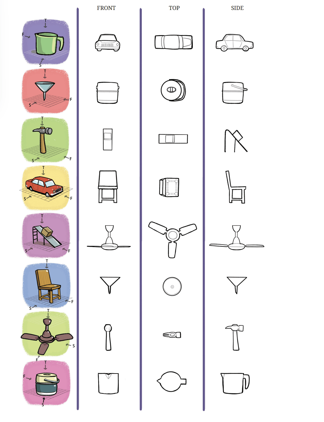
Shadows
Place an object in front of a plane, such as a wall of your room. Shine a torch light on the object in a direction perpendicular to the wall.
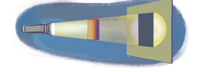
? What do you see?
We will see that the shape of the shadow on a plane is quite similar to the shape of the projection on that plane! However the shadow may be scaled up, stretched, or even distorted slightly, depending on how the object is held.
? Observe what happens to the size of the shadow as you vary the distance between your torch and your object.
? Why does this happen?
Now, imagine your torch is extremely powerful and will continue casting a shadow of the object on the wall, no matter how far back you move it.
If this imaginary torch always points in a direction perpendicular to the wall, then, as the distance between the torch and the object increases, the shadow of the object will become indistinguishable from the projection of the object to the wall plane!
Although this experiment may sound fanciful, you have encountered one such extremely powerful and distant torch before... namely, the Sun! Indeed, when sunlight is perpendicular to a plane, the shadows it casts on that plane are indistinguishable from projections!
Earlier we asked what the projection of a parallelogram might look like. You can now physically answer this question by making a cutout of a parallelogram and viewing its shadows under sunlight. No matter how you orient the parallelogram, you will see that the shadow remains a parallelogram!
This property is useful for drawing projections of objects.
? Figure it Out
1. Draw the top view, front view and the side view of each of the following combinations of identical cubes.
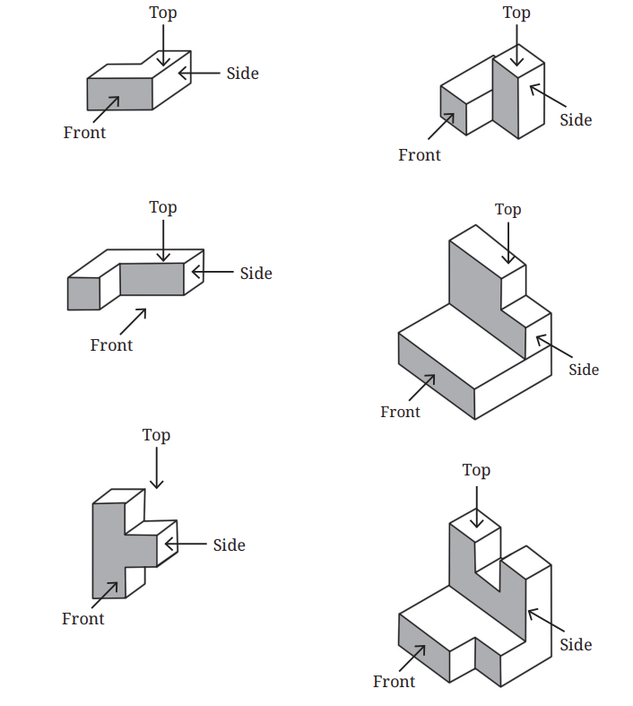
2. Imagine eight identical cubes, glued together along faces to form the letter.

(i) This looks like a
from the front. What does it look like from the side? From the top?
(ii) Glue additional cubes to make a shape that looks like ‘ ’
from the front and ‘  ’ from the top.
(iii) Now, can you glue even more cubes to make it look like ‘ ’
from the front,' '
from the top, and'  ' from the side?
(iv) Can you think of other letter combinations to make with a single combination of cubes in this manner?
3. Which solid corresponds to the given top view, front view, and side view?
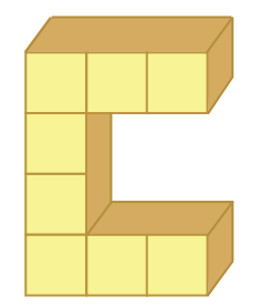
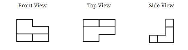
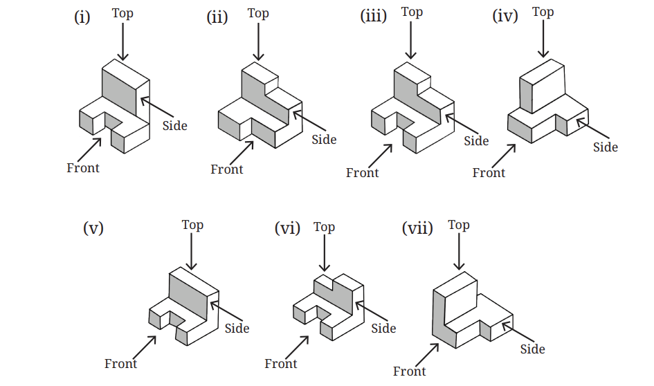
4. Using identical cubes, make a solid that gives the following projections.
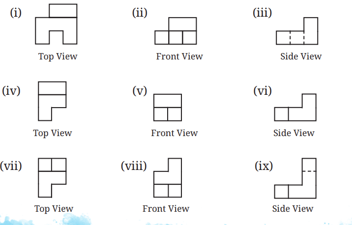
5. Find the number of cubes in this stack of identical cubes.

6. What are the different shapes the projection of a cube can make under different orientations?
Isometric Projections
In general we lose information when projecting a solid to a plane. But depending on the orientation of the solid, we can sometimes recover much of the information we’ve lost.
Let us consider an orientation of a cube in which the lengths of the projections of all the edges of the cube are equal. Such a projection is called the isometric projection of the cube. ‘Isometric’ means ‘equal measure’ in Greek.
Imagine balancing a cube perfectly on one of its corner vertices, and then projecting it down to the floor plane. This projection is isometric and appears as shown.
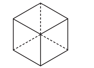
? Construct a model of a cube and use your hands to keep it balanced on one corner vertex. Can you try to understand why all the projected edges have equal length?
The isometric representation of a cube is a regular hexagon. If the cube is made of glass, then all the edges would be visible.
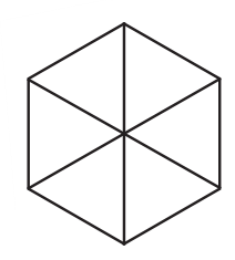
This structure is the basis for isometric drawing! Tile the plane with hexagons and we get an isometric grid.
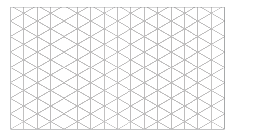
Isometric grids are widely used in engineering. They make it easy to draw projections of solids and to measure lengths along all the 3 primary directions — length, depth and height, as shown in Fig. 4.7.
Drawing on Isometric Grids
? Have you played Tetris? There are five basic shapes in Tetris, corresponding to the different ways of arranging four squares.
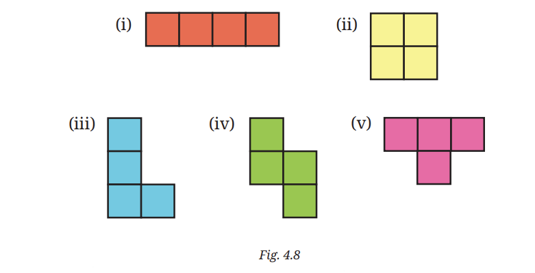
? Imagine these are cubes, not squares. Draw each of these on your isometric paper (you can find it at the end of the book).
As seen in Fig. 4.7, there are three principal axes of the solid shape, which we will call the depth axis, length axis, and height axis.
The edges of the grid appear in three different orientations: /, \ and . We will associate height to |, depth to /, and length to \.
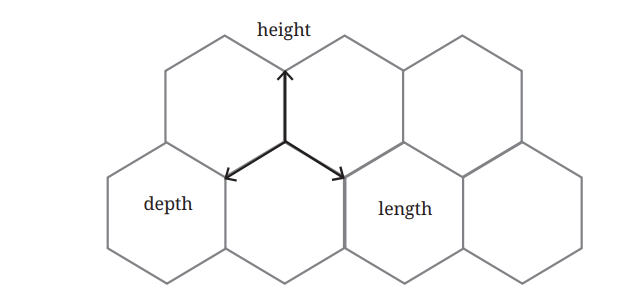
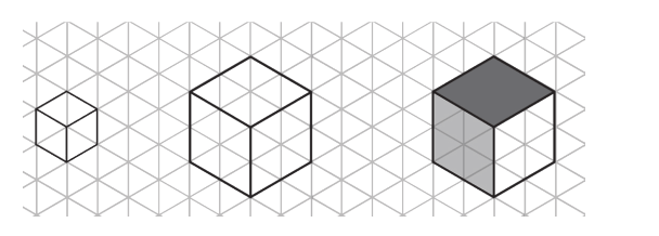
While drawing on the grid, it may be useful to draw edge by edge, counting the number of units you want to go along a given axis.
For example, you can draw a 1 * 1 * 1 cube as follows. How would you draw a 2 * 2 * 2 cube? Feel free to add shading, if it helps you visualise the solid.
The first tetris shape is a row of four cubes joined face-to-face. In order to draw this solid, you will need to choose an orientation for the row of four cubes.
Let's draw it oriented along the depth axis. You could draw it cube-by-cube, but in that case you may need to erase the lines that get hidden by additional cubes. (If you don't have an eraser, you can also draw faint lines initially, and then darken the visible ones later.)
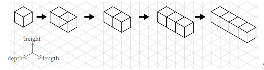
You could also draw it all at once, by counting edges as you go:
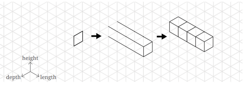
Similarly, you could draw the shape oriented along the height axis or the length axis.
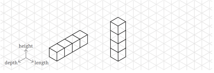
In your drawing, moving in the vertical direction on the isometric paper corresponds to moving along the height axis of the solid. Similarly, moving along the or direction on the paper corresponds to moving along the length or depth axis respectively of the solid.
? Why is this correspondence between directions on isometric paper and axes of the solid so effective for communicating the shape of the solid?
Earlier we observed that parallel lines project to parallel lines. This geometric fact ensures that the three families of parallel edges on the solid (corresponding to height, the length, and depth) project to three families of parallel edges on the isometric paper: |, /, and \. Moreover, the isometric nature of the projection ensures that the projections of unit distances along the three axes are equal.
Can you try drawing the other tetris shapes on isometric paper?
? Figure it Out
1. In addition to the 5 ways shown in Fig. 4.8, are there any additional ways of gluing four cubes together along faces? Can you visualise and draw these as well?
2. Draw the following figures on the isometric grid.
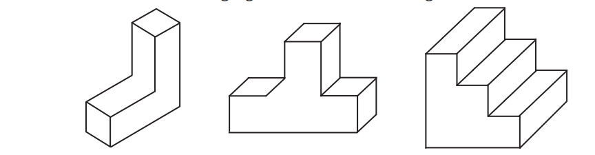
[Hint: It may be useful to determine whether the edge to be currently drawn — say, along the height — goes from down to up or up to down. Accordingly, draw the line segment on the grid either in the direction of the height axis or opposite to it.]
3. Is there anything strange about the path of this ball? Recreate it on the isometric grid.
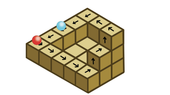
[Hint: Consider a portion of this figure that is physically realisable and identify the 3 primary directions.]
4. Observe this triangle.
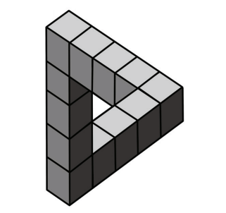
(i) Would it be possible to build a model out of actual cubes? What are the front, top, and side profiles of this impossible triangle?
(ii) Recreate this on an isometric grid.
(iii) Why does the illusion work?
SUMMARY
- Fractals are self-similar geometric objects found in nature and in art.
- The Sierpinski Carpet, Sierpinski Gasket, and Koch Snowflake are some examples of mathematical fractals. They can be obtained by repeatedly applying certain geometric operations that generate a sequence of shapes approaching the fractal.
- Cuboids, tetrahedrons, cylinders, cones, prisms, pyramids, and octahedrons are some of the solids that can be obtained by folding suitable nets
- The shortest path between two points on the surface of a cuboid can be found by using a suitable net of the cuboid.
- Any object can be represented on a plane surface by using its projections on plane surfaces. For this purpose, we generally use the front view (projection on the vertical plane), top view (projection on the horizontal plane), and side view (projection on the side plane) of the object.
- A cube can be oriented such that the lengths of all its edges in the projection are equal. Such a projection is called the isometric projection. Isometric projections of different solids can be drawn using isometric grid paper.