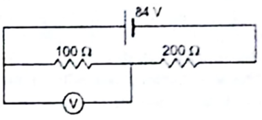
A voltmeter of resistance 400 Ω is used to measure the potential difference across the 100Ω resistor in the circuit shown in figure.
(a) What will be the reading of the voltmeter?
(b) What was the potential difference across 100Ω before the voltmeter was connected?
Concepts/Formula used:
Resistors in Series:
![]()
Resistors in parallel:
![]()
Ohm’s Law:
Potential Difference (V) across a resistor of resistance R when current I passes through it is given by Ohm’s law:
![]()
(a)
The given circuit is:
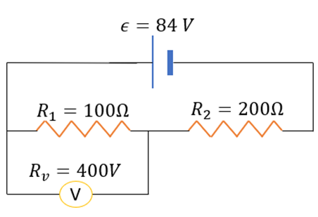
We can easily see that the voltmeter and R1 are in parallel. The equivalent resistance, r’ is given by:
![]()
![]()
We can redraw the circuit as follows:
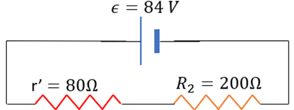
Note that r’ and R2 are in series. The equivalent resistance is given by:
![]()
The current coming out of the battery also passes through r’. By Ohm’s law,
![]()
![]()
Now, the voltmeter reads the potential different across R1 .
![]()
![]()
Hence, the voltmeter reads 24V.
(b)
The given circuit is now:
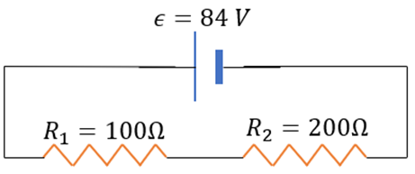
The equivalent resistance is :
![]()
The current is the same throughout the circuit as all components are in series and is given by:
![]()
![]()
Now, the potential difference across R1 is given by:
![]()
![]()
![]()
Hence, the potential difference across the 100Ω resistor before connecting the voltmeter was 28V.