Table of Contents

12
Electricity and Circuits
We use electricity for many purposes to make our tasks easier. For example, we use electricity to operate pumps that lift water from wells or from ground level to the roof top tank. What are other purposes for which you use electricity? List some of them in your notebook.
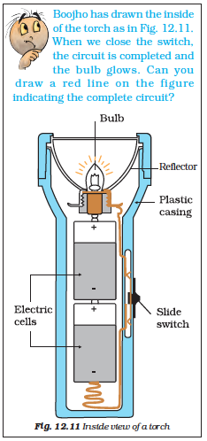
Does your list include the use of electricity for lighting? Electricity makes it possible to light our homes, roads, offices, markets and factories even after sunset. This helps us to continue working at night. A power station provides us with electricity. However, the supply of electricity may fail or it may not be available at some places. In such situations, a torch is sometimes used for providing light. A torch has a bulb that lights up when it is switched on. Where does the torch get electricity from?
12.1. Electric Cell
Caution
 You might have seen the danger sign shown here displayed on poles, electric substations and many other places. It is to warn people that electricity can be dangerous if not handled properly. Carelessness in handling electricity and electric devices can cause severe injuries and sometimes even death. Hence, you should never attempt to experiment with the electric wires and sockets. Also remember that the electricity generated by portable generators is equally dangerous. Use only electric cells for all activities related to electricity.
Electricity to the bulb in a torch is provided by the electric cell. Electric cells are also used in alarm clocks, wristwatches, transistor radios, cameras and many other devices. Have you ever carefully looked at an electric cell? You might have noticed that it has a small metal cap on one side and a metal disc on the other side (Fig. 12.1). Did you notice a positive (+) sign and a negative (–) sign marked on the electric cell? The metal cap is the positive terminal of the electric cell. The metal disc is the negative terminal. All electric cells have two terminals; a positive terminal and a negative terminal.
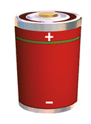
An electric cell produces electricity from the chemicals stored inside it. When the chemicals in the electric cell are used up, the electric cell stops producing electricity. The electric cell then has to be replaced with a new one.

Fig.12.2 (a) Torch bulb and (b) its inside view
A torch bulb has an outer case of glass that is fixed on a metallic base [Fig. 12. 2 (a)]. What is inside the glass case of the bulb?
Activity 1
Take a torch and look inside its bulb. You can also take out the bulb with the help of your teacher. What do you notice? Do you find a thin wire fixed in the middle of the glass bulb [Fig. 12.2 (b)]? Now switch the torch on and observe which part of the bulb is glowing.
The thin wire that gives off light is called the filament of the bulb. The filament is fixed to two thicker wires, which also provide support to it, as shown in Fig. 12.2 (b). One of these thick wires is connected to the metal case at the base of the bulb [Fig. 12.2 (b)]. The other thick wire is connected to the metal tip at the centre of the base. The base of the bulb and the metal tip of the base are the two terminals of the bulb. These two terminals are fixed in such a way that they do not touch each other. The electric bulbs used at home also have a similar design.
Caution: Never join the two terminals of the electric cell without connecting them through a switch and a device like a bulb. If you do so, the chemicals in the electric cell get used up very fast and the cell stops working.
Thus, both the electric cell and the bulb have two terminals each. Why do they have these two terminals?
12.2. A Bulb Connected to an Electric Cell
Let us try to make an electric bulb light up using an electric cell. How do we do that?
Activity 2
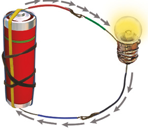
Take four lengths of electric wire with differently coloured plastic coverings. Remove a little of the plastic covering from each length of wire at the ends. This would expose the metal wires at the ends of each length. Fix the exposed parts of two wires to the cell and the other two of the bulb as shown in Fig. 12.3 and Fig. 12.4.


You can stick the wires to the bulb with the tape used by electricians. Use rubber bands or tape to fix the wires to the cell.
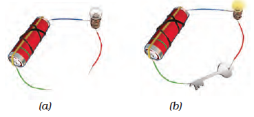
Now, connect the wires fixed to the bulb with those attached to the cell in six different ways as have been shown in Fig. 12.5 (a) to (f).For each arrangement, find out whether the bulb glows or not. Write ‘Yes’ or ‘No’ for each arrangement in your notebook.

Fig.12.5 Different arrangements of electric cell and bulb
Now, carefully look at the arrangements in which the bulb glows. Compare these with those in which the bulb does not glow. Can you find the reason for the difference?
Keep the tip of your pencil on the wire near one terminal of the electric cell for the arrangment in Fig. 12.5 (a). Move the pencil along the wire all the way to the bulb. Now, from the other terminal of the bulb, move along the other wire connected to the cell. Repeat this exercise for all the other arrangements in Fig. 12.5. Did the bulb glow for the arrangements in which you could not move the pencil from one terminal to the other?
12.3 An Electric Circuit
In Activity 2 you connected one terminal of the electric cell to the other terminal through wires passing to and from the electric bulb. Note that in the arrangements shown in Fig. 12. 5 (a) and (f), the two terminals of the electric cell were connected to two terminals of the bulb. Such an arrangement is an example of an electric circuit. The electric circuit provides a complete path for electricity to pass (current to flow) between the two terminals of the electric cell. The bulb glows only when current flows through the circuit.
In an electric circuit, the direction of current is taken to be from the positive to the negative terminal of the electric cell as shown in Fig.12.6.
When the terminals of the bulb are connected with that of the electric cell by wires, the current passes through the filament of the bulb. This makes the bulb glow.
Sometimes an electric bulb does not glow even if it is connected to the cell. This may happen if the bulb has fused. Look at a fused bulb carefully. Is the filament inside it intact?
An electric bulb may fuse due to many reasons. One reason for a bulb to fuse is a break in its filament. A break in the filament of an electric bulb means a break in the path of the current between the terminals of the electric cell. Therefore, a fused bulb does not light up as no current passes through its filament.
Can you now explain why the bulb did not glow when you tried to do so with the arrangements shown in Fig. 12.5 (b), (c), (d) and (e)?
Now we know how to make a bulb light up using an electric cell. Would you like to make a torch for yourself?
Activity 3
Take a torch bulb and a piece of wire. Remove the plastic covering at the two ends of the wire as you did before. Wrap one end of a wire around the base of an electric bulb as shown in Fig. 12.7. Fix the other end of the wire to the negative terminal of an electric cell with a rubber band. Now, bring the tip of the base of the bulb, that is, its other terminal in contact with the positive terminal of the cell. Does the bulb glow?

Now move the bulb away from the terminal of the electric cell. Does the bulb remain lighted? Is this not similar to what you do when you switch your torch on or off?
12.4 Electric Switch
We had an arrangement for switching on or off our home made torch by moving the base of the bulb away from the tip of the cell. This was a simple switch, but, not very easy to use. We can make another simple and easier switch to use in our circuit.
Activity 4
You can make a switch using two drawing pins, a safety pin (or a paper clip), two wires and a small sheet of thermo Col or a wooden board. Insert a drawing pin into the ring at one end of the safety pin and fix it on the thermo Col sheet as shown in Fig. 12.8. Make sure that the safety pin can be rotated freely. Now, fix the other drawing pin on the thermo Col sheet in a way that the free end of the safety pin can touch it. The safety pin fixed in this way would be your switch in this activity.

Now, make a circuit by connecting an electric cell and a bulb with this switch as shown in Fig.12.9. Rotate the safety pin so that its free end touches the other drawing pin. What do you observe? Now, move the safety pin away. Does the bulb continue to glow?
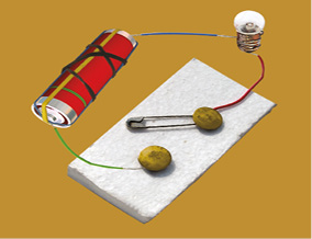
The safety pin covered the gap between the drawing pins when you made it touch two of them. In this position the switch is said to be ‘on’ (Fig. 12.10). Since the material of the safety pin allows the current to pass through it, the circuit was complete. Hence, the bulb glows.

Fig. 12.10 A switch in ‘on’ position
On the other hand, the bulb did not glow when the safety pin was not in touch with the other drawing pin. The circuit was not complete as there was a gap between the two drawing pins. In this position, the switch is said to be ‘off’ as in Fig. 12.9.
A switch is a simple device that either breaks the circuit or completes it. The switches used in lighting of electric bulbs and other devices in homes work on the same principle although their designs are more complex.
12.5 Electric Conductors and Insulators
In all our activities we have used metal wires to make a circuit. Suppose we use a cotton thread instead of a metal wire to make a circuit. Do you think that the bulb will light up in such a circuit? What materials can be used in electric circuits so that the current can pass through them? Let us find out.
Activity 5
Disconnect the switch from the electric circuit you used for Activity 4. This would leave you with two free ends of wires as shown in Fig. 12.12 (a). Bring the free ends of the two wires close, to let them touch each other. Does the bulb light up? You can now use this arrangement to test whether any given material allows current to pass through it or not.
Collect samples of different types of materials such as coins, cork, rubber, glass, keys, pins, plastic scale, wooden block, aluminium foil, candle, sewing needle, thermo Col, paper and pencil lead. One by one bring the free ends of the wires of your tester in contact with two ends of the samples you have collected [Fig. 12.12 (b)]. Make sure that the two wires do not touch each other while you are doing so. Does the bulb glow in each case?
Make a table in your notebook similar to Table.12.1, and record your observations.
Table 12.1 Conductors and insulators

What do you find? The bulb does not glow when the free ends of the wires are in contact with some of the materials you have tested. This means that these materials do not allow the electric current to pass through them. On the other hand, some materials allow electric current to pass through them, which is indicated by the glowing bulb. Materials which allow electric current to pass through them are conductors of electricity. Insulators do not allow electric current to pass through them. With the help of Table 12.1, name the materials that are conductors of electricity and also those which are insulators.
Conductors ______, ______, _________
Insulator _________, _______, ________
What do you conclude? Which materials are conductors and which are insulators? Recall the objects that we grouped as those having lustre, in Chapter 4. Are they the conductors? It now seems easy to understand why copper, aluminum and other metals are used for making wires.
Let us recall Activity 4 in which we made an electric circuit with a switch (Fig.12.9). When the switch was in the open position, were the two drawing pins not connected with each other through the thermo Col sheet? But, thermo Col, you may have found is an insulator. What about the air between the gap? Since the bulb does not glow when there is only air in the gap between the drawing pins in your switch, it means that air is also an insulator.
Conductors and insulators are equally important for us. Switches, electrical plugs and sockets are made of conductors. On the other hand, rubber and plastics are used for covering electrical wires, plug tops, switches and other parts of electrical appliances, which people might touch.
Caution: Your body is a conductor of electricity. Therefore, be careful when you handle an electrical appliance.
Summary
- Electric cell is a source of electricity.
- An electric cell has two terminals; one is called positive (+ ve) while the other is negative (– ve).
- An electric bulb has a filament that is connected to its terminals.
- An electric bulb glows when electric current passes through it.
- In a closed electric circuit, the electric current passes from one terminal of the electric cell to the other terminal.
- Switch is a simple device that is used to either break the electric circuit or to complete it.
- Materials that allow electric current to pass through them are called conductors.
- Materials that do not allow electric current to pass through them are called insulators.
KeyWords
Exercises
1. Fill in the blanks :
(a) A device that is used to break an electric circuit is called _______________.
(b) An electric cell has _______________ terminals.
2. Mark ‘True’ or ‘False’ for following statements:
(a) Electric current can flow through metals.
(b) Instead of metal wires, a jute string can be used to make a circuit.
(c) Electric current can pass through a sheet of thermo Col.
3. Explain why the bulb would not glow in the arrangement shown in Fig. 12.13.

4. Complete the drawing shown in Fig 12.14 to indicate where the free ends of the two wires should be joined to make the bulb glow.

5. What is the purpose of using an electric switch? Name some electrical gadgets that have switches built into them.
6. Would the bulb glow after completing the circuit shown in Fig. 12.14 if instead of safety pin we use an eraser?
7. Would the bulb glow in the circuit shown in Fig. 12.15?

8. Using the “conduction tester” on an object it was found that the bulb begins to glow. Is that object a conductor or an insulator? Explain.
9. Why should an electrician use rubber gloves while repairing an electric switch at your home? Explain.
10. The handles of the tools like screwdrivers and pliers used by electricians for repair work usually have plastic or rubber covers on them. Can you explain why?
SOME SUGGESTED ACTIVITIES
1. Imagine there were no electric supply for a month. How would that affect your day to day activities and others in your family? Present your imagination in the form of a story or a play. If possible stage the play written by you or your friends in school.
2. For your friends, you may set up a game “How steady is your hand?”. You will need a cell, an electric bulb, a metal key, two iron nails ( about 5 cm in length), about one and a half metre long thick metal wire (with its plastic insulation scraped off ) and few pieces of connecting wires. Fix two nails nearly one metre apart on a wooden board so that these can be used as a hook. Fix the wire between the nails after inserting it through the loop of the key. Connect one end of this wire to a bulb and a cell. Connect the other terminal of the cell to the key with a wire. Ask your friend to move the loop along the straight wire without touching it. Glowing of the bulb would indicate that the loop of the key has touched the wire.
3. Read and find out about Alessandro Volta who invented the electric cell. You may also find out about Thomas Alva Edison who invented the electric bulb.