
CHAPTER 13
Our Environment
We have heard the word ‘environment’ often being used on the television, in newspapers and by people around us. Our elders tell us that the ‘environment’ is not what it used to be earlier; others say that we should work in a healthy ‘environment’; and global summits involving the developed and developing countries are regularly held to discuss ‘environmental’ issues. In this chapter, we shall be studying how various factors in the environment interact with each other and how we impact the environment.
13.1 ECO-SYSTEM- WHAT ARE ITS COMPONENTS?
All organisms such as plants, animals, microorganisms and human beings as well as the physical surroundings interact with each other and maintain a balance in nature. All the interacting organisms in an area together with the non-living constituents of the environment form an ecosystem. Thus, an ecosystem consists of biotic components comprising living organisms and abiotic components comprising physical factors like temperature, rainfall, wind, soil and minerals.
For example, if you visit a garden you will find different plants, such as grasses, trees; flower bearing plants like rose, jasmine, sunflower; and animals like frogs, insects and birds. All these living organisms interact with each other and their growth, reproduction and other activities are affected by the abiotic components of ecosystem. So a garden is an ecosystem. Other types of ecosystems are forests, ponds and lakes. These are natural ecosystems while gardens and crop-fields are humanmade (artificial) ecosystems.
Activity 13.1
- You might have seen an aquarium. Let us try to design one.
- What are the things that we need to keep in mind when we create an aquarium? The fish would need a free space for swimming (it could be a large jar), water, oxygen and food.
- We can provide oxygen through an oxygen pump (aerator) and fish food which is available in the market.
- If we add a few aquatic plants and animals it can become a self is an example of a human-made ecosystem.
- Can we leave the aquarium as such after we set it up? Why does it have to be cleaned once in a while? Do we have to clean ponds or lakes in the same manner? Why or why not?
We have seen in earlier classes that organisms can be grouped as producers, consumers and decomposers according to the manner in which they obtain their sustenance from the environment. Let us recall what we have learnt through the self sustaining ecosystem created by us above. Which organisms can make organic compounds like sugar and starch from inorganic substances using the radiant energy of the Sun in the presence of chlorophyll? All green plants and certain bacteria which can produce food by photosynthesis come under this category and are called the producers.
Organisms depend on the producers either directly or indirectly for their sustenance? These organisms which consume the food produced, either directly from producers or indirectly by feeding on other consumers are the consumers. Consumers can be classed variously as herbivores, carnivores, omnivores and parasites. Can you give examples for each of these categories of consumers?
• Imagine the situation where you do not clean the aquarium and some fish and plants have died. Have you ever thought what happens when an organism dies? The microorganisms, comprising bacteria and fungi, break-down the dead remains and waste products of organisms. These microorganisms are the decomposers as they break-down the complex organic substances into simple inorganic substances that go into the soil and are used up once more by the plants. What will happen to the garbage, and dead animals and plants in their absence? Will the natural replenishment of the soil take place, even if decomposers are not there?
Activity 13.2
- While creating an aquarium did you take care not to put an aquatic animal which would eat others? What would have happened otherwise?
- Make groups and discuss how each of the above groups of organisms are dependent on each other.
- Write the aquatic organisms in order of who eats whom and form a chain of at least three steps.
 →
→  →
→ 
-
- Would you consider any one group of organisms to be of primary importance? Why or why not?
13.1.1 Food Chains and Webs
In Activity 13.4 we have formed a series of organisms feeding on one another. This series or organisms taking part at various biotic levels form a food chain (Fig. 13.1).
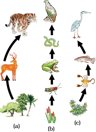
Figure 13.1 Food chain in nature (a) in forest, (b) in grassland and (c) in a pond
Each step or level of the food chain forms a trophic level. The autotrophs or the producers are at the first trophic level. They fix up the solar energy and make it available for heterotrophs or the consumers. The herbivores or the primary consumers come at the second, small carnivores or the secondary consumers at the third and larger carnivores or the tertiary consumers form the fourth trophic level (Fig. 13.2).
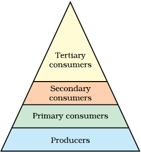
Figure 13.2 Trophic levels
We know that the food we eat acts as a fuel to provide us energy to do work. Thus the interactions among various components of the environment involves flow of energy from one component of the system to another. As we have studied, the autotrophs capture the energy present in sunlight and convert it into chemical energy. This energy supports all the activities of the living world. From autotrophs, the energy goes to the heterotrophs and decomposers. However, as we saw in the previous Chapter on ‘Sources of Energy’, when one form of energy is changed to another, some energy is lost to the environment in forms which cannot be used again. The flow of energy between various components of the environment has been extensively studied and it has been found that –
• The green plants in a terrestrial ecosystem capture about 1% of the energy of sunlight that falls on their leaves and convert it into food energy.
• When green plants are eaten by primary consumers, a great deal of energy is lost as heat to the environment, some amount goes into digestion and in doing work and the rest goes towards growth and reproduction. An average of 10% of the food eaten is turned into its own body and made available for the next level of consumers.
• Therefore, 10% can be taken as the average value for the amount of organic matter that is present at each step and reaches the next level of consumers.
• Since so little energy is available for the next level of consumers, food chains generally consist of only three or four steps. The loss of energy at each step is so great that very little usable energy remains after four trophic levels.
• There are generally a greater number of individuals at the lower trophic levels of an ecosystem, the greatest number is of the producers.
• The length and complexity of food chains vary greatly. Each organism is generally eaten by two or more other kinds of organisms which in turn are eaten by several other organisms. So instead of a straight line food chain, the relationship can be shown as a series of branching lines called a food web (Fig. 13.3).
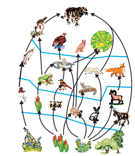
Figure 13.3 Food web, consisting of many food chains
From the energy flow diagram (Fig. 13.4), two things become clear. Firstly, the flow of energy is unidirectional. The energy that is captured by the autotrophs does not revert back to the solar input and the energy which passes to the herbivores does not come back to autotrophs. As it moves progressively through the various trophic levels it is no longer available to the previous level.Secondly, the energy available at each trophic level gets diminished progressively due to loss of energy at each level.
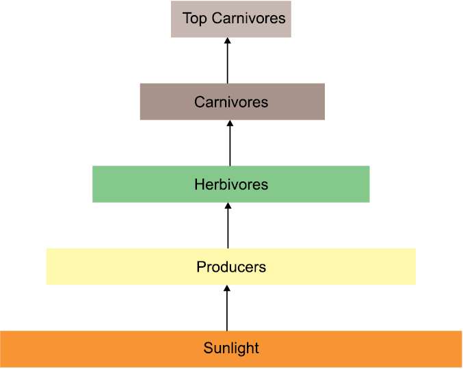
Figure 13.4 Diagram showing flow of energy in an ecosystem
Another interesting aspect of food chain is how unknowingly some harmful chemicals enter our bodies through the food chain. You have read in Class IX how water gets polluted. One of the reasons is the use of several pesticides and other chemicals to protect our crops from diseases and pests. These chemicals are either washed down into the soil or into the water bodies. From the soil, these are absorbed by the plants along with water and minerals, and from the water bodies these are taken up by aquatic plants and animals. This is one of the ways in which they enter the food chain. As these chemicals are not degradable, these get accumulated progressively at each trophic level. As human beings occupy the top level in any food chain, the maximum concentration of these chemicals get accumulated in our bodies. This phenomenon is known as biological magnification. This is the reason why our food grains such as wheat and rice, vegetables and fruits, and even meat, contain varying amounts of pesticide residues. They cannot always be removed by washing or other means.
Activity 13.3
- Newspaper reports about pesticide levels in ready-made food items are often seen these days and some states have banned these products. Debate in groups the need for such bans.
- What do you think would be the source of pesticides in these food items? Could pesticides get into our bodies from this source through other food products too?
- Discuss what methods could be applied to reduce our intake of pesticides.
QUESTIONS
1. What are trophic levels? Give an example of a food chain and state the different trophic levels in it.
2. What is the role of decomposers in the ecosystem?
13.2 HOW DO OUR ACTIVITIES AFFECT THE ENVIRONMENT?
We are an integral part of the environment. Changes in the environment affect us and our activities change the environment around us. We have already seen in Class IX how our activities pollute the environment. In this chapter, we shall be looking at two of the environmental problems in detail, that is, depletion of the ozone layer and waste disposal.
13.2.1 Ozone Layer and How it is Getting Depleted
Ozone (O3) is a molecule formed by three atoms of oxygen. While O2, which we normally refer to as oxygen, is essential for all aerobic forms of life. Ozone, is a deadly poison. However, at the higher levels of the atmosphere, ozone performs an essential function. It shields the surface of the earth from ultraviolet (UV) radiation from the Sun. This radiation is highly damaging to organisms, for example, it is known to cause skin cancer in human beings.
Ozone at the higher levels of the atmosphere is a product of UV radiation acting on oxygen (O2) molecule. The higher energy UV radiations split apart some moleculer oxygen (O2) into free oxygen (O) atoms. These atoms then combine with the molecular oxygen to form ozone as shown—
O2---------UV--------> O+O
O+O2---------------->O3(ozone)
The amount of ozone in the atmosphere began to drop sharply in the 1980s. This decrease has been linked to synthetic chemicals like chlorofluorocarbons (CFCs) which are used as refrigerants and in fire extinguishers. In 1987, the United Nations Environment Programme (UNEP) succeeded in forging an agreement to freeze CFC production at 1986 levels.
Activity 13.4
- Find out from the library, internet or newspaper reports, which chemicals are responsible for the depletion of the ozone layer.
- Find out if the regulations put in place to control the emission of these chemicals have succeeded in reducing the damage to the ozone layer. Has the size of the hole in the ozone layer changed in recent years?
13.2.2 Managing the Garbage we Produce
In our daily activities, we generate a lot of material that are thrown away. What are some of these waste materials? What happens after we throw them away? Let us perform an activity to find answers to these questions.
Activity 13.5
- Collect waste material from your homes. This could include all the waste generated during a day, like kitchen waste (spoilt food, vegetable peels, used tea leaves, milk packets and empty cartons), waste paper, empty medicine bottles/strips/bubble packs, old and torn clothes and broken footwear.
- Bury this material in a pit in the school garden or if there is no space available, you can collect the material in an old bucket/ flower pot and cover with at least 13 cm of soil.
- Keep this material moist and observe at 13-day intervals.
- What are the materials that remain unchanged over long periods of time?
- What are the materials which change their form and structure over time?
- Of these materials that are changed, which ones change the fastest?
We have seen in the chapter on ‘Life Processes’ that the food we eat is digested by various enzymes in our body. Have you ever wondered why the same enzyme does not break-down everything we eat? Enzymes are specific in their action, specific enzymes are needed for the break-down of a particular substance. That is why we will not get any energy if we try to eat coal! Because of this, many human-made materials like plastics will not be broken down by the action of bacteria or other saprophytes. These materials will be acted upon by physical processes like heat and pressure, but under the ambient conditions found in our environment, these persist for a long time.
Substances that are broken down by biological processes are said to be biodegradable. How many of the substances you buried were biodegradable? Substances that are not broken down in this manner are said to be non-biodegradable. These substances may be inert and simply persist in the environment for a long time or may harm the various members of the eco-system.
Activity 13.6
- Use the library or internet to find out more about biodegradable and non-biodegradable substances.
- How long are various non-biodegradable substances expected to last in our environment?
- These days, new types of plastics which are said to be biodegradable are available. Find out more about such materials and whether they do or do not harm the environment.
Visit any town or city, and we are sure to find heaps of garbage all over the place. Visit any place of tourist interest and we are sure to find the place littered with empty food wrappers. In the earlier classes we have talked about this problem of dealing with the garbage that we generate. Let us now look at the problem a bit more deeply.
Activity 13.7
- Find out what happens to the waste generated at home. Is there a system in place to collect this waste?
- Find out how the local body (panchayat, municipal corporation,resident welfare association) deals with the waste. Are there mechanisms in place to treat the biodegradable and non biodegradeble wates separately?
- Calculate how much waste is generated at home in a day.
- How much of this waste is biodegradable?
- Calculate how much waste is generated in the classroom in a day.
- How much of this waste is biodegradable?
- Suggest ways of dealing with this waste.
Activity 13.8
- Find out how the sewage in your locality is treated. Are there mechanisms in place to ensure that local water bodies are not polluted by untreated sewage.
- Find out how the local industries in your locality treat their wastes.Are there mechanisms in place to ensure that the soil and water are not polluted by this waste?
Improvements in our life-style have resulted in greater amounts of waste material generation. Changes in attitude also have a role to play, with more and more things we use becoming disposable. Changes in packaging have resulted in much of our waste becoming nonbiodegradable. What do you think will be the impact of these on our environment?
Think it over
Disposable cups in trains
If you ask your parents, they will probably remember a time when tea in trains was served in plastic glasses which had to be returned to the vendor. The introduction of disposable cups was hailed as a step forward for reasons of hygiene. No one at that time perhaps thought about the impact caused by the disposal of millions of these cups on a daily basis. Some time back, kulhads, that is, disposable cups made of clay, were suggested as an alternative. But a little thought showed that making these kulhads on a large scale would result in the loss of the fertile top-soil. Now disposable paper-cups are being used. What do you think are the advantages of disposable paper-cups over disposable plastic cups?
Activity 13.9
- Search the internet or library to find out what hazardous materials have to be dealt with while disposing of electronic items. How would these materials affect the environment?
- Find out how plastics are recycled. Does the recycling process have any impact on the environment?
QUESTIONS
1. What is ozone and how does it affect any ecosystem?
2. How can you help in reducing the problem of waste disposal? Give any two methods.
What Have We Learnt
- The various components of an ecosystem are interdependent.
- The producers make the energy from sunlight available to the rest of the ecosystem.
- There is a loss of energy as we go from one trophic level to the next, this limits the number of trophic levels in a food-chain.
- Human activities have an impact on the environment.
- The use of chemicals like CFCs has endangered the ozone layer. Since the ozone layer protects against the ultraviolet radiation from the Sun, this could damage the environment.
- The waste we generate may be biodegradable or non-biodegradable.
- The disposal of the waste we generate is causing serious environmental problems.
Exercises
1. Which of the following groups contain only biodegradable items?
(a) Grass, flowers and leather
(b) Grass, wood and plastic
(c) Fruit-peels, cake and lime-juice
(d) Cake, wood and grass
2. Which of the following constitute a food-chain?
(a) Grass, wheat and mango
(b) Grass, goat and human
(c) Goat, cow and elephant
(d) Grass, fish and goat
3. Which of the following are environment-friendly practices?
(a) Carrying cloth-bags to put purchases in while shopping
(b) Switching off unnecessary lights and fans
(c) Walking to school instead of getting your mother to drop you on her scooter
(d) All of the above
4. What will happen if we kill all the organisms in one trophic level?
5. Will the impact of removing all the organisms in a trophic level be different for different trophic levels? Can the organisms of any trophic level be removed without causing any damage to the ecosystem?
6. What is biological magnification? Will the levels of this magnification be different at different levels of the ecosystem?
7. What are the problems caused by the non-biodegradable wastes that we generate?
8. If all the waste we generate is biodegradable, will this have no impact on the environment?
9. Why is damage to the ozone layer a cause for concern? What steps are being taken to limit this damage?