Table of Contents
Chapter Ten

Mechanical Properties of Fluids
9.1 Introduction
9.2 Pressure
9.3 Streamline flow
9.4 Bernoulli’s principle
9.5 Viscosity
9.6 Surface tension
Summary
Points to ponder
Exercises
Additional exercises
Appendix
9.1 Introduction
In this chapter, we shall study some common physical properties of liquids and gases. Liquids and gases can flow and are therefore, called fluids. It is this property that distinguishes liquids and gases from solids in a basic way.
Fluids are everywhere around us. Earth has an envelop of air and two-thirds of its surface is covered with water. Water is not only necessary for our existence; every mammalian body constitute mostly of water. All the processes occurring in living beings including plants are mediated by fluids. Thus understanding the behaviour and properties of fluids is important.
How are fluids different from solids? What is common in liquids and gases? Unlike a solid, a fluid has no definite shape of its own. Solids and liquids have a fixed volume, whereas a gas fills the entire volume of its container. We have learnt in the previous chapter that the volume of solids can be changed by stress. The volume of solid, liquid or gas depends on the stress or pressure acting on it. When we talk about fixed volume of solid or liquid, we mean its volume under atmospheric pressure. The difference between gases and solids or liquids is that for solids or liquids the change in volume due to change of external pressure is rather small. In other words solids and liquids have much lower compressibility as compared to gases.
Shear stress can change the shape of a solid keeping its volume fixed. The key property of fluids is that they offer very little resistance to shear stress; their shape changes by application of very small shear stress. The shearing stress of fluids is about million times smaller than that of solids.
9.2 Pressure
A sharp needle when pressed against our skin pierces it. Our skin, however, remains intact when a blunt object with a wider contact area (say the back of a spoon) is pressed against it with the same force. If an elephant were to step on a man’s chest, his ribs would crack. A circus performer across whose est a large, light but strong wooden plank is placed first, is saved from this accident. Such everyday experiences convince us that both the force and its coverage area are important. Smaller the area on which the force acts, greater is the impact. This impact is known as pressure.
When an object is submerged in a fluid at rest, the fluid exerts a force on its surface. This force is always normal to the object’s surface. This is so because if there were a component of force parallel to the surface, the object will also exert a force on the fluid parallel to it; as a consequence of Newton’s third law. This force will cause the fluid to flow parallel to the surface. Since the fluid is at rest, this cannot happen. Hence, the force exerted by the fluid at rest has to be perpendicular to the surface in contact with it. This is shown in Fig.9.1(a).
The normal force exerted by the fluid at a point may be measured. An idealised form of one such pressure-measuring device is shown in Fig. 9.1(b). It consists of an evacuated chamber with a spring that is calibrated to measure the force acting on the piston. This device is placed at a point inside the fluid. The inward force exerted by the fluid on the piston is balanced by the outward spring force and is thereby measured.

(a) (b)
Fig. 9.1 (a) The force exerted by the liquid in the beaker on the submerged object or on the walls is normal (perpendicular) to the surface at all points.
(b) An idealised device for measuring pressure.
In principle, the piston area can be made arbitrarily small. The pressure is then defined in a limiting sense as
P = 
 (9.2)
(9.2)
Pressure is a scalar quantity. We remind the reader that it is the component of the force normal to the area under consideration and not the (vector) force that appears in the numerator in Eqs. (9.1) and (9.2). Its dimensions are [ML–1T–2]. The SI unit of pressure is N m–2. It has been named as pascal (Pa) in honour of the French scientist Blaise Pascal (1623-1662) who carried out pioneering studies on fluid pressure. A common unit of pressure is the atmosphere (atm), i.e. the pressure exerted by the atmosphere at sea level (1 atm = 1.013 × 10⁵ Pa).
Another quantity, that is indispensable in describing fluids, is the density ρ. For a fluid of mass m occupying volume V,
p = m / v (9.3)
The dimensions of density are [ML–3]. Its SI unit is kg m–3. It is a positive scalar quantity. A liquid is largely incompressible and its density is therefore, nearly constant at all pressures. Gases, on the other hand exhibit a large variation in densities with pressure.
The density of water at 4oC (277 K) is 1.0 × 10³ kg m–3. The relative density of a substance is the ratio of its density to the density of water at 4oC. It is a dimensionless positive scalar quantity. For example the relative density of aluminium is 2.7. Its density is
2.7 × 10³ kg m–3. The densities of some common fluids are displayed in Table 9.1.

Table 9.1 Densities of some common fluids at STP*
*STP means standard temperature (00C) and 1 atm pressure.
Example 9.1 The two thigh bones (femurs), each of cross-sectional area10 cm2 support the upper part of a human body of mass 40 kg. Estimate the average pressure sustained by the femurs.
Answer Total cross-sectional area of the femurs is A = 2 × 10 cm2 = 20 × 10–4 m2. The force acting on them is F = 40 kg wt = 400 N (taking g = 10 m s–2). This force is acting vertically down and hence, normally on the femurs. Thus, the average pressure is
Pav = F/A = 2*105 N m-29.2.1 Pascal’s Law
The French scientist Blaise Pascal observed that the pressure in a fluid at rest is the same at all points if they are at the same height. This fact may be demonstrated in a simple way.
Fb sinθ = Fc' Fb cosθ = Fa (by equilibrium)
Ab sinθ = Ac' Ab cosθ = Aa (by geometry)
Thus,
Fb / Ab = Fc / Ac = Fa / Aa : Pb = Pc = Pa (9.4)
Hence, pressure exerted is same in all directions in a fluid at rest. It again reminds us that like other types of stress, pressure is not a vector quantity. No direction can be assigned to it. The force against any area within (or bounding) a fluid at rest and under pressure is normal to the area, regardless of the orientation of the area.
Now consider a fluid element in the form of a horizontal bar of uniform cross-section. The bar is in equilibrium. The horizontal forces exerted at its two ends must be balanced or the pressure at the two ends should be equal. This proves that for a liquid in equilibrium the pressure is same at all points in a horizontal plane. Suppose the pressure were not equal in different parts of the fluid, then there would be a flow as the fluid will have some net force acting on it. Hence in the absence of flow the pressure in the fluid must be same everywhere in a horizontal plane.
9.2.2 Variation of Pressure with Depth
Consider a fluid at rest in a container. In Fig. 9.3 point 1 is at height h above a point 2. The pressures at points 1 and 2 are P1 and P2 respectively. Consider a cylindrical element of fluid having area of base A and height h. As the fluid is at rest the resultant horizontal forces should be zero and the resultant vertical forces should balance the weight of the element. The forces acting in the vertical direction are due to the fluid pressure at the top (P1A) acting downward, at the bottom (P2A) acting upward. If mg is weight of the fluid in the cylinder we have
(P2 − P1) A = mg (9.5)
Now, if ρ is the mass density of the fluid, we have the mass of fluid to be m = ρV= ρhA so that
P2 − P1= ρgh (9.6)

Fig.9.3 Fluid under gravity. The effect of gravity is illustrated through pressure on a vertical cylindrical column.
Pressure difference depends on the vertical distance h between the points (1 and 2), mass density of the fluid ρ and acceleration due to gravity g. If the point 1 under discussion is shifted to the top of the fluid (say, water), which is open to the atmosphere, P1 may be replaced by atmospheric pressure (Pa) and we replace P2 by P. Then Eq. (9.6) gives
P = Pa + ρgh (9.7)
Thus, the pressure P, at depth below the surface of a liquid open to the atmosphere is greater than atmospheric pressure by an amount ρgh. The excess of pressure, P − Pa, at depth h is called a gauge pressure at that point.
The area of the cylinder is not appearing in the expression of absolute pressure in Eq. (9.7). Thus, the height of the fluid column is important and not cross-sectional or base area or the shape of the container. The liquid pressure is the same at all points at the same horizontal level (same depth). The result is appreciated through the example of hydrostatic paradox. Consider three vessels A, B and C [Fig.9.4] of different shapes. They are connected at the bottom by a horizontal pipe. On filling with water, the level in the three vessels is the same, though they hold different amounts of water. This is so because water at the bottom has the same pressure below each section of the vessel.

Example 9.2 What is the pressure on a swimmer 10 m below the surface of a lake?
Answer Here
h = 10 m and ρ = 1000 kg m-3. Take g = 10 m s–2
From Eq. (9.7)
9.2.3 Atmospheric Pressure and Gauge Pressure
The pressure of the atmosphere at any point is equal to the weight of a column of air of unit cross-sectional area extending from that point to the top of the atmosphere. At sea level, it is 1.013 × 10⁵ Pa (1 atm). Italian scientist Evangelista Torricelli (1608–1647) devised for the first time a method for measuring atmospheric pressure. A long glass tube closed at one end and filled with mercury is inverted into a trough of mercury as shown in Fig.9.5 (a). This device is known as ‘mercury barometer’. The space above the mercury column in the tube contains only mercury vapour whose pressure P is so small that it may be neglected. Thus, the pressure at Point A=0. The pressure inside the coloumn at Point B must be the same as the pressure at Point C, which is atmospheric pressure, Pa.
Pa = ρgh (9.8)
where ρ is the density of mercury and h is the height of the mercury column in the tube.
In the experiment it is found that the mercury column in the barometer has a height of about 76 cm at sea level equivalent to one atmosphere (1 atm). This can also be obtained using the value of ρ in Eq. (9.8). A common way of stating pressure is in terms of cm or mm of mercury (Hg). A pressure equivalent of 1 mm is called a torr (after Torricelli).
1 torr = 133 Pa.
The mm of Hg and torr are used in medicine and physiology. In meteorology, a common unit is the bar and millibar.
1 bar = 105 Pa
An open tube manometer is a useful instrument for measuring pressure differences. It consists of a U-tube containing a suitable liquid i.e., a low density liquid (such as oil) for measuring small pressure differences and a high density liquid (such as mercury) for large pressure differences. One end of the tube is open to the atmosphere and the other end is connected to the system whose pressure we want to measure [see Fig. 9.5 (b)]. The pressure P at A is equal to pressure at point B. What we normally measure is the gauge pressure, which is P − Pa, given by Eq. (9.8) and is proportional to manometer height h.

Fig 9.5 (a) The mercury barometer.

(b)The open tube manometer
Fig 9.5 Two pressure measuring devices.
Example 9.3 The density of the atmosphere at sea level is 1.29 kg/m3. Assume that it does not change with altitude. Then how high would the atmosphere extend?
Answer We use Eq. (9.7)
ρgh = 1.29 kg m–3 × 9.8 m s2 × h m = 1.01 × 10⁵ Pa
∴ h = 7989 m ≈ 8 km
In reality the density of air decreases with height. So does the value of g. The atmospheric cover extends with decreasing pressure over 100 km. We should also note that the sea level atmospheric pressure is not always 760 mm of Hg. A drop in the Hg level by 10 mm or more is a sign of an approaching storm.
Example 9.4 At a depth of 1000 m in an ocean (a) what is the absolute pressure? (b) What is the gauge pressure? (c) Find the force acting on the window of area 20 cm × 20 cm of a submarine at this depth, the interior of which is maintained at sea-level atmospheric pressure. (The density of sea water is 1.03 × 10³ kg m-3, g = 10 m s–2.)
Answer Here h = 1000 m and ρ = 1.03 × 10³ kg m-3.
(a) From Eq. (9.6), absolute pressure
P = Pa + ρgh
= 1.01 × 10⁵ Pa
+ 1.03 × 10³ kg m–3 × 10 m s–2 × 1000 m
= 104.01 × 10⁵ Pa
(b) Gauge pressure is P − Pa = ρgh = Pg
Pg = 1.03 × 10³ kg m–3 × 10 ms2 × 1000 m
= 103 × 105 Pa
≈ 103 atm
(c) The pressure outside the submarine is P = Pa + ρgh and the pressure inside it is Pa. Hence, the net pressure acting on the window is gauge pressure, Pg = ρgh. Since the area of the window is A = 0.04 m2, the force acting on it is
F = Pg A = 103 × 105 Pa × 0.04 m2 = 4.12 × 10⁵ N
Let us now consider what happens when we change the pressure on a fluid contained in a vessel. Consider a horizontal cylinder with a piston and three vertical tubes at different points [Fig. 9.6 (a)]. The pressure in the horizontal cylinder is indicated by the height of liquid column in the vertical tubes. It is necessarily the same in all. If we push the piston, the fluid level rises in all the tubes, again reaching the same level in each one of them.

Fig 9.6 (a) Whenever external pressure is applied on any part of a fluid in a vessel, it is equally transmitted in all directions.
This indicates that when the pressure on the cylinder was increased, it was distributed uniformly throughout. We can say whenever external pressure is applied on any part of a fluid contained in a vessel, it is transmitted undiminished and equally in all directions. This is another form of the Pascal’s law and it has many applications in daily life.
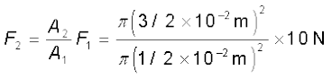
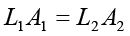
A number of devices, such as hydraulic lift and hydraulic brakes, are based on the Pascal’s law. In these devices, fluids are used for transmitting pressure. In a hydraulic lift, as shown in Fig. 9.6 (b), two pistons are separated by the space filled with a liquid. A piston of small cross-section A1 is used to exert a force F1 directly on the liquid. The pressure P = F1 / A1 is transmitted throughout the liquid to the larger cylinder attached with a larger piston of area A2, which results in an upward force of P × A2. Therefore, the piston is capable of supporting a large force (large weight of, say a car, or a truck, placed on the platform) F2 = PA2 = F1A1 / A1 . By changing the force at A1, the platform can be moved up or down. Thus, the applied force has been increased by a factor of A2 /A1 and this factor is the mechanical advantage of the device. The example below clarifies it.

Fig 9.6 (b) Schematic diagram illustrating the principle behind the hydraulic lift, a device used to lift heavy loads.
Example 9.5 Two syringes of different cross-sections (without needles) filled with water are connected with a tightly fitted rubber tube filled with water. Diameters of the smaller piston and larger piston are 1.0 cm and 3.0 cm respectively. (a) Find the force exerted on the larger piston when a force of 10 N is applied to the smaller piston. (b) If the smaller piston is pushed in through 6.0 cm, how much does the larger piston move out?
Answer (a) Since pressure is transmitted undiminished throughout the fluid,
= 90 N
(b) Water is considered to be perfectly incompressible. Volume covered by the movement of smaller piston inwards is equal to volume moved outwards due to the larger piston.

= 0.67 × 10⁻² m = 0.67 cm
Note, atmospheric pressure is common to both pistons and has been ignored.
Example 9.6 In a car lift compressed air exerts a force F1 on a small piston having a radius of 5.0 cm. This pressure is transmitted to a second piston of radius 15 cm (Fig 9.7). If the mass of the car to be lifted is 1350 kg, calculate F1. What is the pressure necessary to accomplish this task? (g = 9.8 ms-2).
Answer Since pressure is transmitted undiminished throughout the fluid,
= 1470 N
≈ 1.5 × 10³ N
The air pressure that will produce this force is
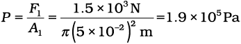
Hydraulic brakes in automobiles also work on the same principle. When we apply a little force on the pedal with our foot the master piston moves inside the master cylinder, and the pressure caused is transmitted through the brake oil to act on a piston of larger area. A large force acts on the piston and is pushed down expanding the brake shoes against brake lining. In this way, a small force on the pedal produces a large retarding force on the wheel. An important advantage of the system is that the pressure set up by pressing pedal is transmitted equally to all cylinders attached to the four wheels so that the braking effort is equal on all wheels.
9.3 STREAMLINE FLOW
So far we have studied fluids at rest. The study of the fluids in motion is known as fluid dynamics. When a water tap is turned on slowly, the water flow is smooth initially, but loses its smoothness when the speed of the outflow is increased. In studying the motion of fluids, we focus our attention on what is happening to various fluid particles at a particular point in space at a particular time. The flow of the fluid is said to be steady if at any given point, the velocity of each passing fluid particle remains constant in time. This does not mean that the velocity at different points in space is same. The velocity of a particular particle may change as it moves from one point to another. That is, at some other point the particle may have a different velocity, but every other particle which passes the second point behaves exactly as the previous particle that has just passed that point. Each particle follows a smooth path, and the paths of the particles do not cross each other.

Fig.9.7 The meaning of streamlines. (a) A typical trajectory of a fluid particle. (b) A region of streamline flow.
The path taken by a fluid particle under a steady flow is a streamline. It is defined as a curve whose tangent at any point is in the direction of the fluid velocity at that point. Consider the path of a particle as shown in Fig.9.7 (a), the curve describes how a fluid particle moves with time. The curve PQ is like a permanent map of fluid flow, indicating how the fluid streams. No two streamlines can cross, for if they do, an oncoming fluid particle can go either one way or the other and the flow would not be steady. Hence, in steady flow, the map of flow is stationary in time. How do we draw closely spaced streamlines ? If we intend to show streamline of every flowing particle, we would end up with a continuum of lines. Consider planes perpendicular to the direction of fluid flow e.g., at three points P, R and Q in Fig.9.7 (b). The plane pieces are so chosen that their boundaries be determined by the same set of streamlines. This means that number of fluid particles crossing the surfaces as indicated at P, R and Q is the same. If area of cross-sections at these points are AP,AR and AQ and speeds of fluid particles are vP, vR and vQ, then mass of fluid ∆mP crossing at AP in a small interval of time ∆t is ρPAPvP ∆t. Similarly mass of fluid ∆mR flowing or crossing at AR in a small interval of time ∆t is ρRARvR ∆t and mass of fluid ∆mQ is ρQAQvQ ∆t crossing at AQ. The mass of liquid flowing out equals the mass flowing in, holds in all cases. Therefore,
ρPAPvP∆t = ρRARvR∆t = ρQAQvQ∆t (9.9)
For flow of incompressible fluids
ρP = ρR = ρQ
Equation (9.9) reduces to
APvP = ARvR = AQvQ (9.10)
which is called the equation of continuity and it is a statement of conservation of mass in flow of incompressible fluids. In general
Av = constant (9.11)
Av gives the volume flux or flow rate and remains constant throughout the pipe of flow. Thus, at narrower portions where the streamlines are closely spaced, velocity increases and its vice versa. From (Fig.9.7b) it is clear that AR > AQ or vR < vQ, the fluid is accelerated while passing from R to Q. This is associated with a change in pressure in fluid flow in horizontal pipes.
Steady flow is achieved at low flow speeds. Beyond a limiting value, called critical speed, this flow loses steadiness and becomes turbulent. One sees this when a fast flowing stream encounters rocks, small foamy whirlpool-like regions called ‘white water rapids are formed.
Figure 9.8 displays streamlines for some typical flows. For example, Fig. 9.8(a) describes a laminar flow where the velocities at different points in the fluid may have different magnitudes but their directions are parallel. Figure 9.8 (b) gives a sketch of turbulent flow.
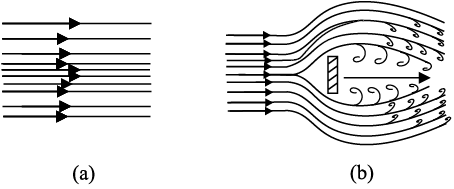
Fig.9.8 (a) Some streamlines for fluid flow. (b) A jet of air striking a flat plate placed perpendicular to it. This is an example of turbulent flow.
9.4 BERNOULLI’S PRINCIPLE
Fluid flow is a complex phenomenon. But we can obtain some useful properties for steady or streamline flows using the conservation of energy.
Consider a fluid moving in a pipe of varying cross-sectional area. Let the pipe be at varying heights as shown in Fig. 9.9. We now suppose that an incompressible fluid is flowing through the pipe in a steady flow. Its velocity must change as a consequence of equation of continuity. A force is required to produce this acceleration, which is caused by the fluid surrounding it, the pressure must be different in different regions. Bernoulli’s equation is a general expression that relates the pressure difference between two points in a pipe to both velocity changes (kinetic energy change) and elevation (height) changes (potential energy change). The Swiss Physicist Daniel Bernoulli developed this relationship in 1738.
Consider the flow at two regions 1 (i.e., BC) and 2 (i.e., DE). Consider the fluid initially lying between B and D. In an infinitesimal time interval ∆t, this fluid would have moved. Suppose v1 is the speed at B and v2 at D, then fluid initially at B has moved a distance v1∆t to C (v1∆t is small enough to assume constant cross-section along BC). In the same interval ∆t the fluid initially at D moves to E, a distance equal to v2∆t. Pressures P1 and P2 act as shown on the plane faces of areas A1 and A2 binding the two regions. The work done on the fluid at left end (BC) is W1 = P1A1(v1∆t) = P1∆V. Since the same volume ∆V passes through both the regions (from the equation of continuity) the work done by the fluid at the other end (DE) is W2 = P2A2(v2∆t) = P2∆V or, the work done on the fluid is –P2∆V. So the total work done on the fluid is
W1 – W2 = (P1− P2) ∆V
Part of this work goes into changing the kinetic energy of the fluid, and part goes into changing the gravitational potential energy. If the density of the fluid is ρ and ∆m = ρA1v1∆t = ρ∆V is the mass passing through the pipe in time ∆t, then change in gravitational potential energy is
∆U = ρg∆V (h2 − h1)
The change in its kinetic energy is
∆K = 1/2 ρ ∆V (v22 − v12)
We can employ the work – energy theorem (Chapter 6) to this volume of the fluid and this yields
(P1− P2) ∆V = 1/ 2 ρ ∆V (v22 − v12) + ρg∆V (h2 − h1)
We now divide each term by ∆V to obtain
(P1− P2) = 1/ 2 ρ (v22 − v12) + ρg (h2 − h1)
We can rearrange the above terms to obtain
P1 +  ρv12 + ρgh1 = P2+
  ρv22 + ρgh2 (9.12)
This is Bernoulli’s equation. Since 1 and 2 refer to any two locations along the pipeline, we may write the expression in general as
P +  ρv2 + ρgh = constant (9.13)
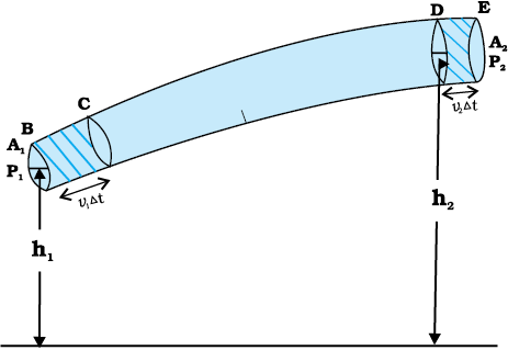
Fig.9.9 The flow of an ideal fluid in a pipe of varying cross section. The fluid in a section of length v1∆t moves to the section of length v2∆t in time ∆t.
In words, the Bernoulli’s relation may be stated as follows: As we move along a streamline the sum of the pressure (P), the kinetic energy per unit volume [ pv2 / 2] and the potential energy per unit volume (ρgh) remains a constant.
Note that in applying the energy conservation principle, there is an assumption that no energy is lost due to friction. But in fact, when fluids flow, some energy does get lost due to internal friction. This arises due to the fact that in a fluid flow, the different layers of the fluid flow with different velocities. These layers exert frictional forces on each other resulting in a loss of energy. This property of the fluid is called viscosity and is discussed in more detail in a later section. The lost kinetic energy of the fluid gets converted into heat energy. Thus, Bernoulli’s equation ideally applies to fluids with zero viscosity or non-viscous fluids. Another restriction on application of Bernoulli theorem is that the fluids must be incompressible, as the elastic energy of the fluid is also not taken into consideration. In practice, it has a large number of useful applications and can help explain a wide variety of phenomena for low viscosity incompressible fluids. Bernoulli’s equation also does not hold for non-steady or turbulent flows, because in that situation velocity and pressure are constantly fluctuating in time.
When a fluid is at rest i.e., its velocity is zero everywhere, Bernoulli’s equation becomes
P1 + ρgh1 = P2 + ρgh2
(P1− P2) = ρg (h2 − h1)
which is same as Eq. (9.6).
9.4.1 Speed of Efflux: Torricelli’s Law
The word efflux means fluid outflow. Torricelli discovered that the speed of efflux from an open tank is given by a formula identical to that of a freely falling body. Consider a tank containing a liquid of density ρ with a small hole in its side at a height y1 from the bottom (see Fig. 9.10). The air above the liquid, whose surface is at height y2, is at pressure P. From the equation of continuity [Eq. (9.10)] we have
v1 A1 = v2 A2
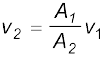
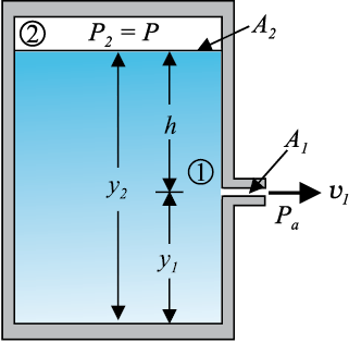
Fig. 9.10 Torricelli’s law. The speed of efflux, v1, from the side of the container is given by the application of Bernoulli’s equation. If the container is open at the topto the atmosphere then  .
.
If the cross-sectional area of the tank A2 is much larger than that of the hole (A2 >>A1), then we may take the fluid to be approximately at rest at the top, i.e., v2