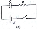
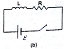
The switches in figure (a) and (b) are closed at t = 0 and reopened after a long time at t = t0.
Formula used:
The charge on capacitor at time t, when the switch is closed is
![]()
Where Q is the Charge
![]() is the emf
is the emf
T is the Time period
R is the Resistance
C is the Capacitance
At t=0, the charge on the capacitor is
![]()
After a long time ![]() , the charge on the capacitor is
, the charge on the capacitor is
![]()
![]()
The current in inductor L is given by
![]()
Where I is the current
![]() is the voltage or potential difference
is the voltage or potential difference
R is the Resistance
L is the inductance
T is the time period
At initial we take, t=0, the current in the inductor is given by
![]()
![]()
After a long time ![]() =
=![]() is
is
![]()
![]()
![]()
The charge on C long after t=0 is ![]()
The current in L long after t = t0 is ![]()
1