Write the truth table for the circuit shown in Fig.14.11. Name the gate that the circuit resembles.
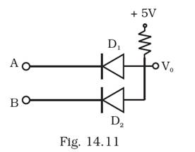
When A and B both are 0, D1 and D2 are in forward bias. Hence, output is 0.
When either A or B is 0 and the other one is 1, the diode with input 1 turns off. Hence, output is 0.
When A and B both are 1, D1 and D2 are in reverse bias. Hence, output is 1.
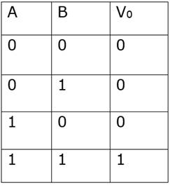
The circuit is AND gate.
1