Draw the output signals C1 and C2 in the given combination of gates (Fig. 14.15).
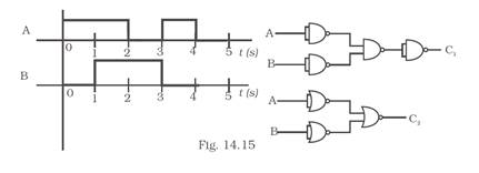
Gate Diagram:
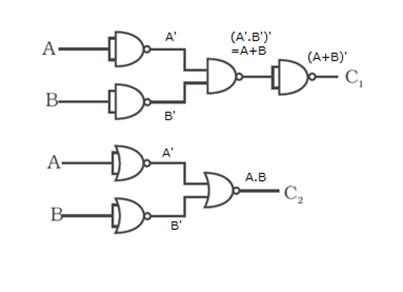
Here ![]()


C2=A.B
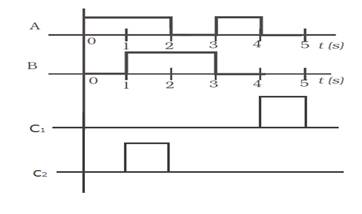
The output will look like,
1
Draw the output signals C1 and C2 in the given combination of gates (Fig. 14.15).
Gate Diagram:
Here ![]()
C2=A.B
The output will look like,