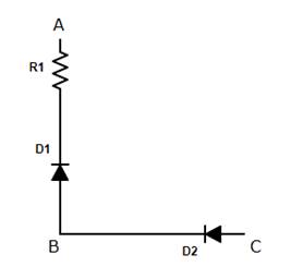
Consider a box with three terminals on top of it as shown in Fig.14.18 (a):
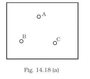
Three components namely, two germanium diodes and one resistor are connected across these three terminals in some arrangement.
A student performs an experiment in which any two of these three terminals are connected in the circuit shown in Fig. 14.18 (b).
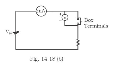
The student obtains graphs of current-voltage characteristics for unknown combination of components between the two terminals connected in the circuit.
The graphs are
(i) when A is positive and B is negative
(ii) when A is negative and B is positive
(iii) When B is negative and C is positive
(iv) When B is positive and C is negative
(v) When A is positive and C is negative
(vi) When A is negative and C is positive
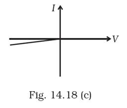
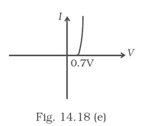
From these graphs of current – voltage characteristic shown in Fig. 14.18 (c) to (h), determine the arrangement of components between A, B and C.
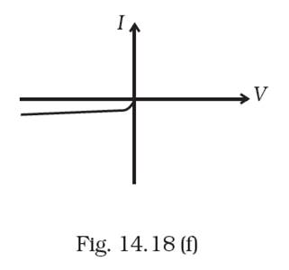
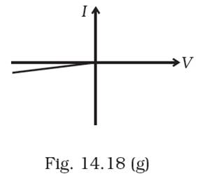
The first diagram is of the reverse bias of diode.
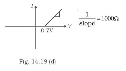
The 2nd diagram is simple ohm’s law but having a turn on voltage 0.7 volts.
Also slop =1000Ω.
Hence, R=1kΩ
That means a diode in a series connection with a 1kΩ resistance.
Furthermore, the 3rd and 4th diagram represents a diode in reverse and forward bias.
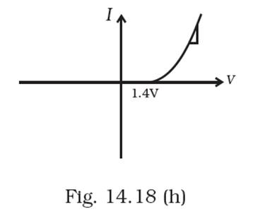
The last two diagrams shows a turn on potential of 1.4v. This is quite certain for having two 0.7v batteries in series or in other words both the diode is in same orientation.
The final structure will be as shown.