You are given two circuits as shown in Fig. 14.46, which consist of NAND gates. Identify the logic operation carried out by the two circuits.
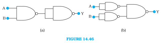
The circuit (a) is as follows:
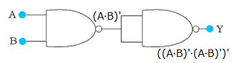
The first NAND gate gives the output (A∙B)’. The second NAND gate gives the output ((A∙B)’∙(A∙B)’)’.
Using De Morgan’s law,
((A∙B)’∙(A∙B)’)’ = ((A∙B)’)’ + ((A∙B)’)’ = (A∙B) + (A∙B) = A∙B (Since, A + A = A)
So, the output is Y = A∙B. The circuit acts as an AND gate.
The truth table for the circuit is as follows:
Input (A) | Output (B) | (A∙B)’ | Output (Y) |
0 | 0 | 1 | 0 |
0 | 1 | 1 | 0 |
1 | 0 | 1 | 0 |
1 | 1 | 0 | 1 |
The circuit (b) is as follows:
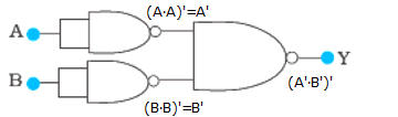
The first NAND gate gives (A∙A)’ = A’ as the output. The second NAND gate gives (B∙B)’ = B’ as the output. The last NAND gate gives (A’∙B’)’ as the output.
Using De Morgan’s law,
(A’∙B’)’ = (A’)’ + (B’)’ = A + B
So, the output is A + B. The circuit acts as an OR gate.
The truth table for the circuit is as follows:
Input (A) | Input (B) | A’ | B’ | Output (Y) |
0 | 0 | 1 | 1 | 0 |
0 | 1 | 1 | 0 | 1 |
1 | 0 | 0 | 1 | 1 |
1 | 1 | 0 | 0 | 1 |
NOTE: NAND gate is a universal gate because it can be used to implement any Boolean function without using any other gates.