Write the truth table for circuit given in Fig. 14.47 below consisting of NOR gates and identify the logic operation (OR, AND, NOT) which this circuit is performing.
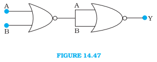
(Hint: A = 0, B = 1 then A and B inputs of second NOR gate will be 0 and hence Y = 1. Similarly, work out the values of Y for other combinations of A and B. Compare with the truth table of OR, AND, NOT gates and find the correct one.)
The given circuit is as follows:
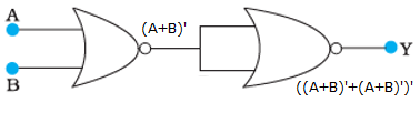
The first NOR gate gives the output (A + B)’. The second NOR gate gives the output ((A + B)’ + (A + B)’)’.
Using De Morgan’s law,
((A + B)’ + (A + B)’)’ = ((A + B)’)’∙((A + B)’)’ = (A + B)∙(A + B) = A + B (Since, A∙A = A)
So, the output is Y = A + B and the circuit acts as an OR gate.
The truth table for the given circuit is as follows:
Input (A) | Input (B) | Output (Y) |
0 | 0 | 0 |
0 | 1 | 1 |
1 | 0 | 1 |
1 | 1 | 1 |
NOTE: NOR gate is a universal gate because it can be used to implement any Boolean function without using any other gates.