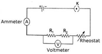
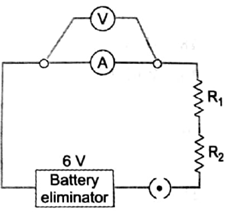
In an experiment to find the equivalent resistance of a series combination of two resistors R1 and R2, a student uses the circuit shown here. Will the circuit give the correct reading for current I and voltage V? Justify your answer.
OR
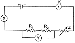
The given circuit diagram shows the experimental arrangement of different circuit components for determination of equivalent resistance of two resistors connected in series. Identify the components X, Y and Z shown in the circuit respectively.
The experimental setup given in the diagram will not give the correct reading of voltage ‘V’, but will give the correct reading of the current ‘I’ in the circuit as voltmeter should be connected in parallel with the resistors in order to measure the drop across the resistors.
OR
The experimental setup is to evaluate the equivalent resistance of 2 resistor in series. The required instruments are a voltmeter, an ammeter and a rheostat. The ammeter is always connected in series as it measures the total current in the circuit, voltmeter in parallel as it measures the net voltage drop across the resistors and the rheostat is connected to control the current flow in the circuit. The complete diagram is given as,