AIM
To draw the images of an object formed by a convex lens when placed at various positions.
MATERIALS REQUIRED
A drawing board, sheets of white paper, measuring scale, protractor and drawing pins or adhesive tape.
THEORY
The light ray when refracted through a convex lens obey the laws of refraction. The formation of images by a convex lens can be studied by drawing ray diagrams. using the new cartesian sign convention as given in the figure.
The new cartesian sign convention can be summarised as below:
(i) The object is always placed to the left of the lens.
(ii) All distances parallel to the principal axis are measured from the optical centre of the lens.
(iii) All distances measured to the right of the origin are taken as positive while those measured to the left of original taken as negative.
(iv) Distance measured perpendicular to and above the principal axis are taken as positive.
(v) Distances measured perpendicular to and below the principal axis are taken as negative.
Daw ray diagrams are forming images by a convex lens for various positions of the object.
The position of the object may be
(a) beyond 2F1
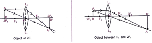
(b) at 2F1
(c) between F1 and 2F1,

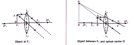
(d) at F1,

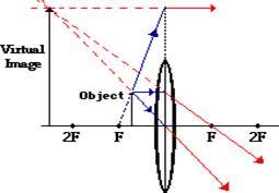
(e) between focus (F1) and optical centre (O) of the convex lens.
PROCEDURE
1. Place a white sheet of paper on a drawing board using pins and cello tape.
2. Draw a thin line 20 cm in length in the middle of the paper using a sharp pencil and a meter scale. Name it as XX’.
3. Mark a point ‘O’ at the centre of this line. Draw a perpendicular line of equal height at the point O as the optical centre above and below XX’. Name it L1L2.
4. Mark points F1 and F2 on the line ‘XX on either side of the lens L1L2 such that OF1 = OF2 where F1 and F2 are the two principal foci of the lens.
5. Also, mark points R1 and R2 on the line XX’ such that O(R1) = 2(OF1) and O(R2)= 2 (OF2).
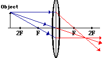
6. Draw the object AB of suitable height ‘h1’ at a very far distance from the lens considered to be placed at infinity.
7. Draw thin lines parallel to the principal axis such as CD, GH, PQ and RS incident on the surface of the convex lens.
8. Draw the emergent rays on the other side of the lens such as DF HF QF and SF through the convex lens and intersect at the first focus F.
9. Record the result in an observation table.
10. Fix second white sheet of paper on the drawing board.
11. Repeat the steps (2) to (6).
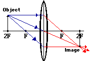
12. Draw an object AB of suitable height beyond 2F1 as shown.
13. Draw a ray of light AE parallel to the principal axis F1OF2 incident on the surface of the convex lens at point E.
14. Draw another ray AO through the optical centre O of a convex lens and extend it to another side of the lens as OA.’
15. On the other side of the convex lens, draw the ray EF2 passing through the focus F2 and intersecting the ray OA’ at A as shown in the figure, forming an image B’A.
16. Measure the height of the image A’B’(h2).
17. We observe from the figure that the image formed is real, inverted, smaller in size and in between F2 and 2F2.
18. Record the reading in the table
19. Repeat the above steps similar to the previous case. Draw ray diagrams for other positions of the object as shown in the
20. Measure the height of the object AB (h1) and height of image A’B’(h2) respective in all cases (c) to (f) as listed in step 20. Record them in the observation table.
21. Note down nature. Relative size and position of the image formed by the convex lens for the various positions of the object.
22. Tabulate your observations in the observation table.
OBSERVATION AND CALCULATION
S. No. |
Position of the object |
Figure No. |
The position of the image |
Nature of the image |
Size of the object (h1) |
Size of the image (h2) |
Magnification h2/h1 |
1. |
At infinity |
(a) |
10 cm |
real |
1 cm |
0 cm |
0 cm |
2. |
Beyond 2F1 |
(b) |
17 cm |
Real, inverted |
1 cm |
0.5 cm |
0.5 cm |
3. |
At 2F1 |
(c) |
20 cm |
Real, inverted |
1 cm |
1 cm |
1 cm |
4. |
Between F1 and 2F1 |
(d) |
35 cm |
Real, inverted |
1 cm |
3 cm |
3 cm |
5. |
At focus F1 |
(e) |
∞ cm |
Real |
1 cm |
∞ cm |
∞ cm |
6. |
Between focus F1 and optical centre O |
(f) |
-25 cm |
Virtual, erect |
1 cm |
5 cm |
5 cm |
RESULT
1. As the object is moved from infinity towards the optical centre of the convex lens.(i) The image distance increases gradually
(ii) Size of the image also increases gradually
2. When the object is placed At infinity, real and highly diminished image is formed at the focus.
3. When the object is placed At Beyond 2F1, real, inverted and smaller image is formed at a point between F1 and F2.
4. When the object is placed At the 2F2 real, inverted and same size of the image of the object is formed at 2F2.
5. When the object lies between F1 and the 2F2 real, inverted and enlarged image is formed beyond 2F2.
6. When the position of th object lies at F1, the image formed is at infinity, It is real, inverted and highly enlarged.
PRECAUTIONS
1. The convex lens should be thin and have a small aperture and should be without any scratches to get the distinct image of the object.
2. The lens should be placed completely vertically inside the lens holder.
3. The ray diagram should be drawn with a sharp pencil.